223
Specifications Section 6-1
Note 1. Refer to Dimensions on page 359 for details on the Unit’s dimensions.
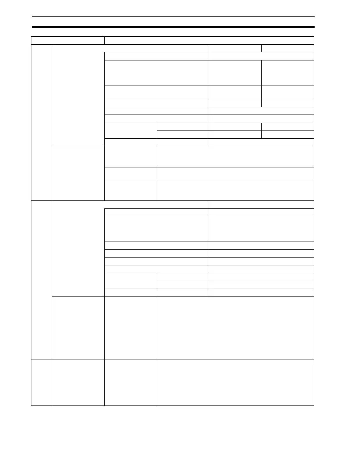
Input Specifications Voltage input Current input
Number of analog inputs 4
Input signal range (See note 3.) 1 to 5 V
0 to 5 V
0 to 10 V
–10 to 10 V
4 to 20 mA
(See note 4.)
Maximum rated input (for 1 point) (See note
5.)
±15 V ±30 mA
Input impedance 1 MΩ min. 250 Ω (rated value)
Resolution 4,000 (full scale)
Converted output data 16-bit binary data
Accuracy
(See note 6.)
23±2°C ±0.2% of full scale ±0.4% of full scale
0°C to 55°C ±0.4% of full scale ±0.6% of full scale
A/D conversion time (See note 7.) 1.0 ms/point max.
Functions Mean value process-
ing
Stores the last “n” data conversions in the buffer, and stores the
the mean value of the conversion values.
Buffer number: n = 2, 4, 8, 16, 32, 64
Peak value holding Stores the maximum conversion value while the Peak Value Hold
Bit is ON.
Input disconnection
detection (See note
9.)
Detects the disconnection and turns ON the Disconnection Detec-
tion Flag.
Output Specifications Voltage output
Number of analog outputs 4
Output signal range
(See note 3.)
1 to 5 V
0 to 5 V
0 to 10 V
–10 to 10 V
Output impedance (for 1 point) 0.5 Ω max.
Max. output current 12 mA
Resolution 4,000 (full scale)
Set data 16-bit binary data
Accuracy
(See note 6.)
23±2°C ±0.3% of full scale
0°C to 55°C ±0.5% of full scale
D/A conversion time (See note 7.) 1.0 ms/point max.
Functions Output hold function Outputs the specified output status (CLR, HOLD, or MAX) under
any of the following circumstances.
When the Conversion Enable Bit is OFF. (See note 8.)
In adjustment mode, when a value other than the output number is
output during adjustment.
When there is an output setting error or a fatal error occurs at the
PLC.
When the CPU Unit is on standby.
When the Load is OFF.
Other Functions Ratio conversion
function
Stores the results of positive and negative gradient analog inputs
calculated for ratio and bias as analog output values.
Positive gradient: Analog output = A × Analog input + B
(A = 0 to 99.99, B = 8,000 to 7FFF Hex)
Negative gradient: Analog output = F – A × Analog input + B
(A = 0 to 99.99, B = 8,000 to 7FFF Hex,
F = output range max. value)
Item CS1W-MAD44
 Loading...


