250
Exchanging Data with the CPU Unit Section 6-5
Allocations for Normal
Mode
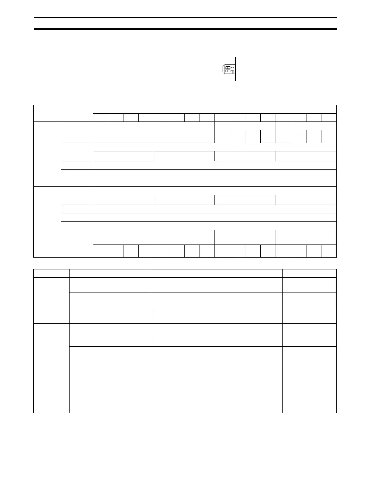
For normal mode, set the operation mode switch on the rear panel of the Unit
as shown in the following diagram.
The allocation of words and bits in the CIO Area is shown in the following
table.
Set Values and Stored Values
Note For the CIO word addresses, n = CIO 2000 + unit number x 10.
I/O Word Bits
1514131211109876543210
Output
(CPU to
Unit)
n Not used. Peak value hold Conversion enable
Input
4
Input
3
Input
2
Input
1
Out-
put 4
Out-
put 3
Out-
put 2
Out-
put 1
n + 1 Output 1 set value
16
3
16
2
16
1
16
0
n + 2 Output 2 set value
n + 3 Output 3 set value
n + 4 Output 4 set value
Input
(Unit to
CPU)
n + 5 Input 1 conversion value / Loop 1 calculation result
16
3
16
2
16
1
16
0
n + 6 Input 2 conversion value / Loop 2 calculation result
n + 7 Input 3 conversion value / Loop 3 calculation result
n + 8 Input 4 conversion value / Loop 4 calculation result
n + 9 Alarm Flags Disconnection detec-
tion
Output setting error
Input
4
Input
3
Input
2
Input
1
Out-
put 4
Out-
put 3
Out-
put 2
Out-
put 1
I/O Item Contents Page
Input Peak value hold function 0: Not used.
1: Peak value hold used.
257
Conversion value
Calculation result
16-bit binary data 253
Disconnection detection 0: No disconnection
1: Disconnection
258
Output Conversion enable 0: Conversion output stopped.
1: Conversion output begun.
260
Set value 16-bit binary data 260
Output setting error 0: No error
1: Output setting error
262
Common Alarm Flags Bits 00 to 03: Output set value error
Bits 04 to 07: Input disconnection detection
Bit 08: Ratio conversion use setting error
Bit 09: Ratio set value error
Bit 10: Output hold setting error
Bit 11: Mean value processing setting error
Bit 15: Operating in adjustment mode
(always 0 in normal mode)
282
283
 Loading...


