256
Analog Input Functions and Operating Procedures Section 6-6
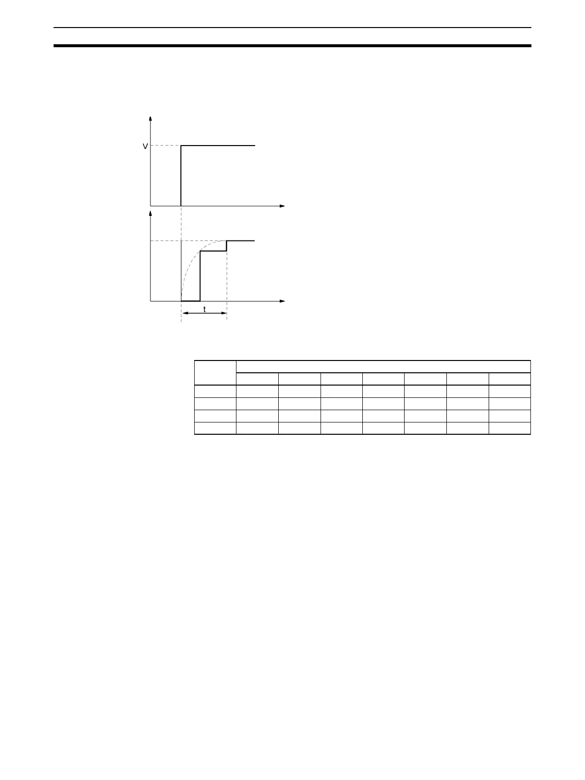
the delay in the conversion data in comparison to changes in the input sig-
nals will be as shown in the following diagram.
2. Specify “no mean value processing” to follow conversion of a rapid change
in input signals.
Response Time Unit: ms
Symbols m: Number of input words used in DM Area
n: Average number of buffers set for the input number for which to find the
response time
Calculation Example The following example calculations are for a resolution of 8,000 with an appli-
cation using inputs 1 and 4, 64 averaging buffers set for input 1, and no aver-
aging set for input 4.
• Response time for input 1: t = {(64
− 2) x 2 + 10.5} = 134.5 (ms)
• Response time for input 1: t = 1 x (2 + 2) = 4 (ms)
Input signal
to the Unit (V)
Conversion data
Time (ms)
Time (ms)
t: Delay
For V = 20 V (−10 to 10 V)
Using One Word
t = n + (2 to 3)
Using m Words (1
≤ m ≤ 8)
No averaging (n = 1) or two averaging buffers (n = 2):
t = n x (m + 2)
n averaging buffers (4
≤ n ≤ 64):
t = (n
− 2) x m + 10.5
mn
64 32 16 8 4 2 1
4 258.5 130.5 66.5 34.5 18.5 12 6
3 196.5 100.5 52.5 28.5 16.5 10 5
2 134.5 70.5 38.5 22.5 14.5 8 4
1 673519117 5 3
 Loading...


