321
Analog Input Functions and Operating Procedures Section 7-6
Device to make the settings in D(m+6) to D(m+9) as shown in the following
table.
For the DM word addresses, m = D20000 + (unit number x 100)
Note After making the DM settings from a Programming Device, it will be necessary
to either turn the power to the PLC OFF and ON, or turn ON the Special I/O
Unit Restart Bit to transfer the contents of the DM settings to the Special I/O
Unit.
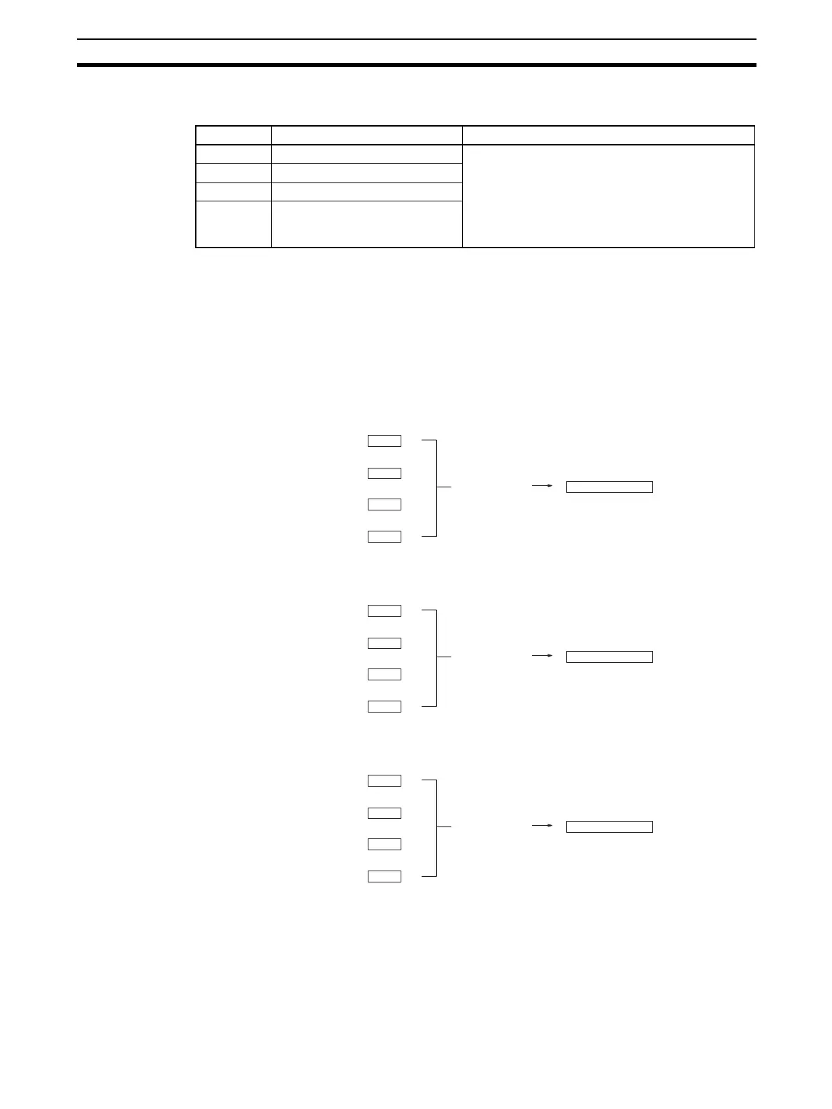
The history buffer operational means are calculated as shown below. (In this
example, there are four buffers.)
1,2,3... 1. With the first cycle, Data 1 is stored in all the history buffers.
Mean value = (Data 1 + Data 1 + Data 1 + Data 1)
÷ 4
2. With the second cycle, Data 2 is stored in the first history buffer.
Mean value = (Data 2 + Data 1 + Data 1 + Data 1)
÷ 4
3. With the third cycle, Data 3 is stored in the first history buffer.
Mean value = (Data 3 + Data 2 + Data 1 + Data 1)
÷ 4
DM word Function Set value
D(m+6) Input 1 mean value processing 0000: Mean value processing with 2 buffers
0001: No mean value processing
0002: Mean value processing with 4 buffers
0003: Mean value processing with 8 buffers
0004: Mean value processing with 16 buffers
0005: Mean value processing with 32 buffers
0006: Mean value processing with 64 buffers
D(m+7) Input 2 mean value processing
D(m+8) Input 3 mean value processing
D(m+9) Input 4 mean value processing
(Mean value
processing)
Conversion value
Data 1
Data 1
Data 1
Data 1
(Mean value
processing)
Conversion value
Data 2
Data 1
Data 1
Data 1
(Mean value
processing)
Conversion value
Data 3
Data 2
Data 1
Data 1
 Loading...


