325
Analog Input Functions and Operating Procedures Section 7-6
Note For decimal numbers −32,000 to +32,000, set 16-bit binary data (8300 to
7D00).
Example Setting 1 Set the following conditions in D(m+27) to D(m+34). (The values shown in
parentheses are binary data.)
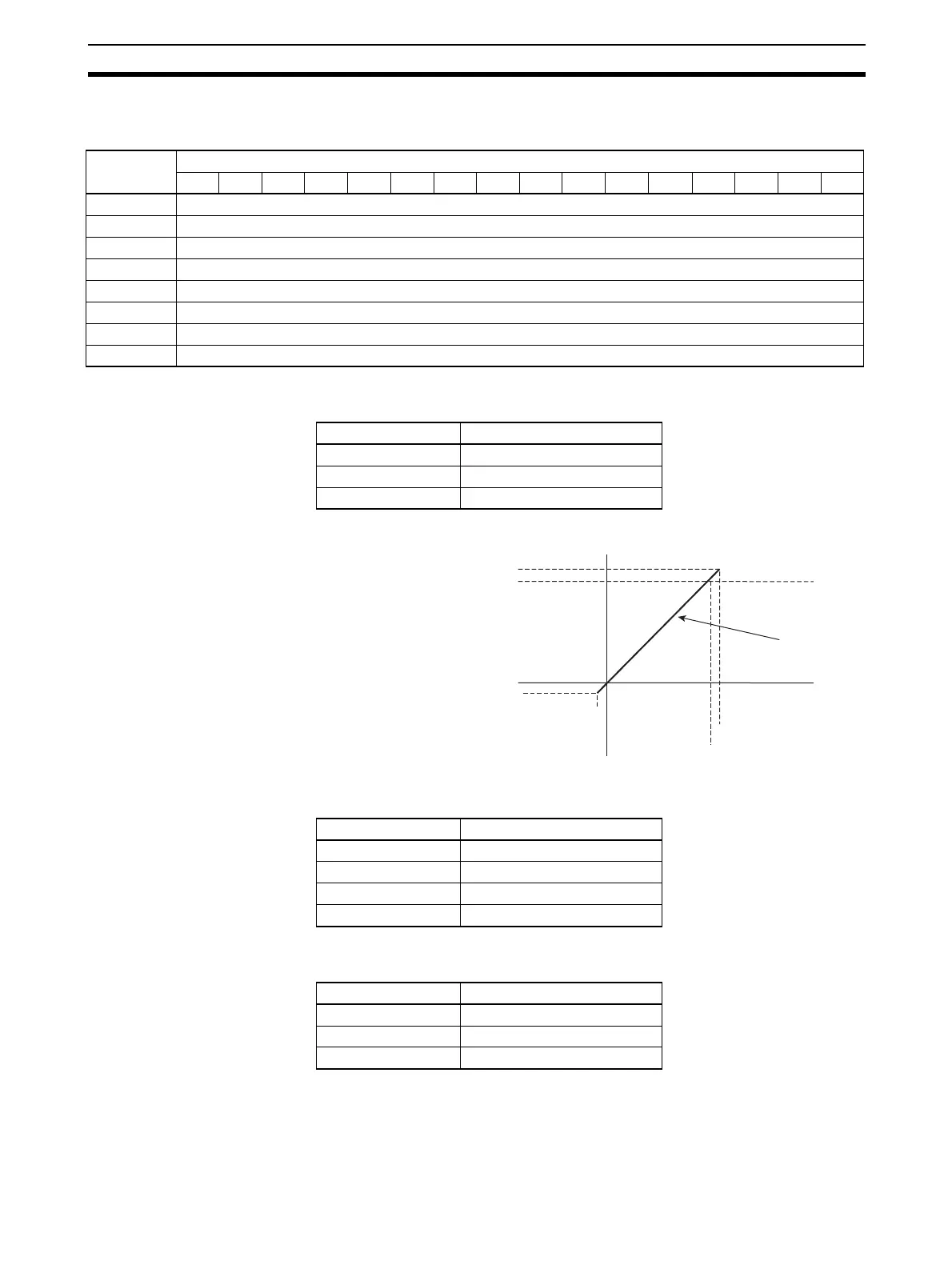
When Input Signal Range is 0 V to 10 V
The following table shows the correspondence between input signals and
converted scaling values. (The values shown in parentheses are binary data.)
Example Setting 2
(Reverse Scaling)
Set the following conditions in D(m+27) to D(m+34). (The values shown in
parentheses are binary data.)
DM word Bits
1514131211109876543210
D(m+27) Input 1 scaling lower limit
D(m+28) Input 1 scaling upper limit
D(m+29) Input 2 scaling lower limit
D(m+30) Input 2 scaling upper limit
D(m+31) Input 3 scaling lower limit
D(m+32) Input 3 scaling upper limit
D(m+33) Input 4 scaling lower limit
D(m+34) Input 4 scaling upper limit
Setting condition Set value
Input signal range 0 to 10 V
Scaling lower limit 0000 (0000)
Scaling upper limit 10,000 (2710)
Input signal Conversion result
0 V 0000 (0000)
10 V 10,000 (2710)
−0.5 V −500 (FE0C)
10.5 V 10,500 (2904)
Offset upper limit 10500 (2904)
Scaling upper limit 10000 (2710)
Scaling lower limit −500 (FE0C)
Offset lower limit 0000 (0000)
Scaling line
0 V
−0.5 V
+10.0 V
+10.5 V
Setting condition Set value
Input signal range 0 to 10 V
Scaling lower limit 10000 (2710)
Scaling upper limit 0000 (0000)
 Loading...


