328
Analog Output Functions and Operating Procedures Section 7-7
gramming Device to set the D(m+1) bits in the DM Area shown in the following
diagram.
Note 1. For the DM word addresses, m = D20000 + (unit number x 100).
2. After making the DM settings from a Programming Device, it will be neces-
sary to either turn the power to the PLC OFF and ON, or turn ON the Spe-
cial I/O Unit Restart Bit to transfer the contents of the DM settings to the
Special I/O Unit.
Voltage/Current Range
Setting
When “1 to 5 V, 4 to 20 mA” is selected for the output signal range, either the
“1 to 5 V” or “4 to 20 mA” range can then be selected by means of the
D(m+35) setting. Adjusting the factory-set voltage and current can improve
the accuracy of current output specifications.
Writing Set Values Analog output set values are written to CIO words (n+1) and (n+2).
For the CIO word addresses, n = CIO 2000 + (unit number x 10).
Use MOV(021) or XFER(070) to write values in the user program.
Example 1 In this example, the set value from only one input is read. (The unit number is
0.)
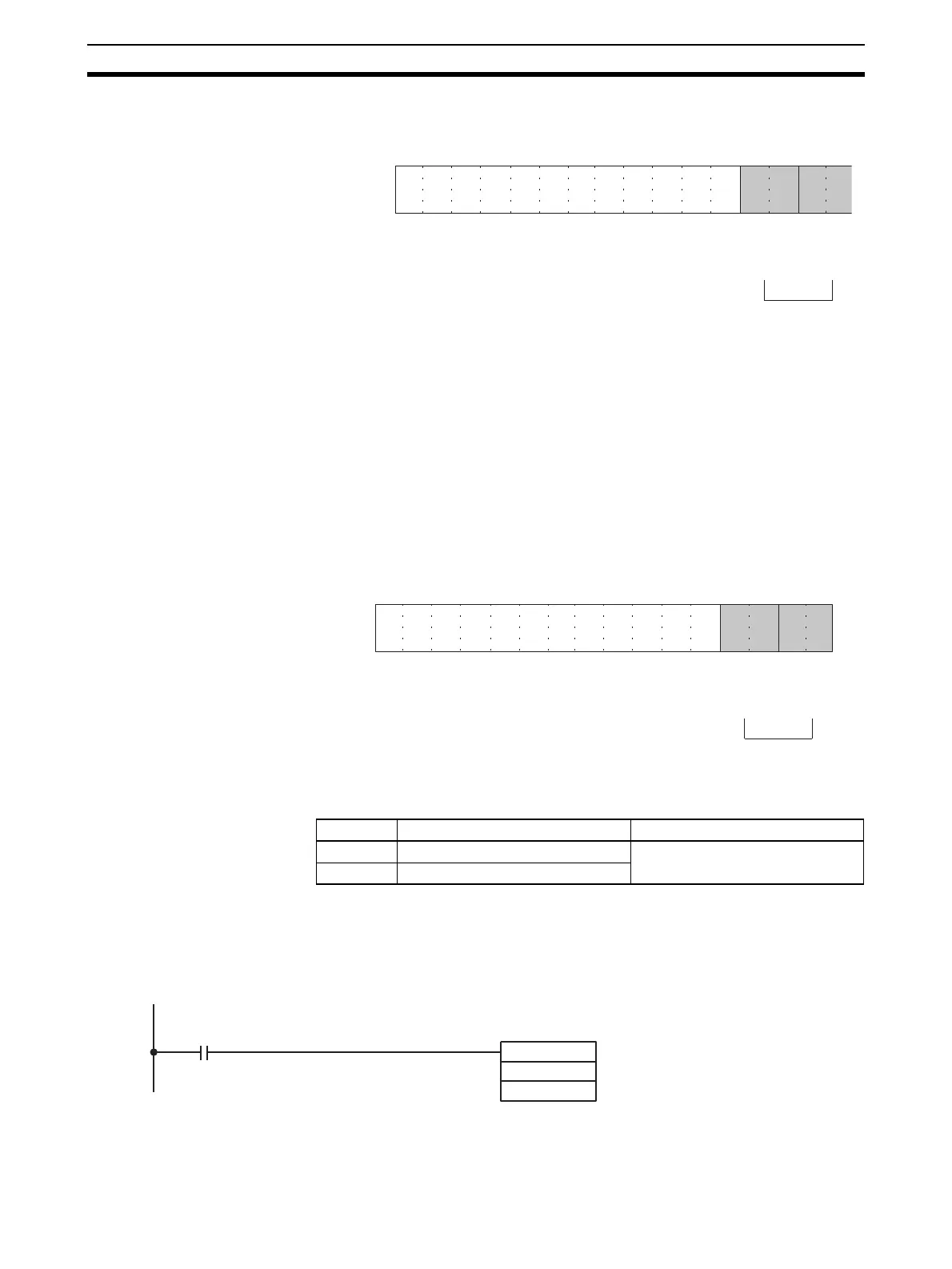
15 14 13 12 11 10 09 08 07 06 05 04 03 02 01 00Bit
D(m + 1)
Output 2
Output 1
00: −10 to 10 V
01: 0 to 10 V
10: 1 to 5 V
11: 0 to 5 V
15 14 13 12 11 10 09 08 07 06 05 04 03 02 01 00Bit
D(m+35)
Output 2
Output 1
0: Voltage: 1 V to 5 V
1: Current 4 mA to 20 mA
Word Function Stored value
n+1 Output 1 set value 16-bit binary data
n+2 Output 2 set value
MOV (021)
D00001
2001
Input condition
The set value stored in D 00001
is written to CIO word 2001 (out-
put number 1).
 Loading...


