26
Operating Procedure Section 2-2
• The following table shows the addresses used for analog input.
Note 1. The addresses are fixed according to the unit number of the Special I/O
Unit. Refer to 2-3-2 Unit Number Switch for further details.
2. Set as required.
3. The input Disconnection Detection Flag is allocated to bits 00 to 07 of word
(n + 9). Refer to Allocations for Normal Mode on page 47 for further details.
Input number Input signal range Input conversion
value address
(n = CIO 2010)
(See note 1.)
Conversion data
holding address
(See note 2.)
1 1 to 5 V (n+1) = CIO 2011 D00100
2 1 to 5 V (n+2) = CIO 2012 D00101
3 4 to 20 mA (n+3) = CIO 2013 D00102
4 4 to 20 mA (n+4) = CIO 2014 D00103
5 0 to 10 V (n+5) = CIO2015 D00104
6 0 to 10 V (n+6) = CIO2016 D00105
7 –10 to 10 V (n+7) = CIO2017 D00106
8 Not used --- ---
201900 Input 1 Disconnection Detection Flag (See note 3.)
201901 Input 2 Disconnection Detection Flag (See note 3.)
201902 Input 3 Disconnection Detection Flag (See note 3.)
201903 Input 4 Disconnection Detection Flag (See note 3.)
For 1 to 5 V, the hexadecimal value 0000
to 0FA0 will be stored in CIO 2011, so if
there is no disconnection (i.e., 201900 is
OFF), CIO 2011 will be stored in
D00100.
In the same way, for 1 to 5 V, CIO 2012
will be stored in D00101.
In the same way, for 4 to 20 mA, CIO 2013
will be stored in D00102.
In the same way, for 4 to 20 mA, CIO 2014
will be stored in D00103.
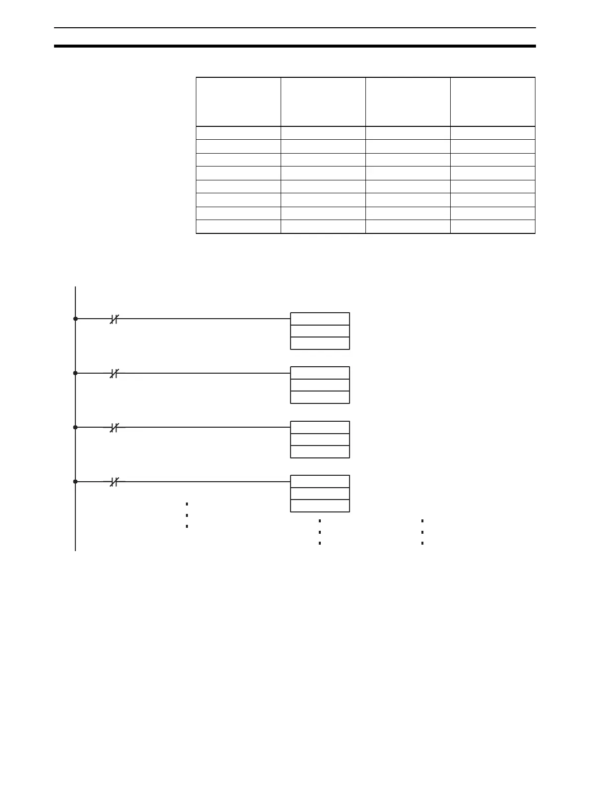
MOV (021)
2011
D00100
MOV (021)
2012
D00101
MOV (021)
2013
D00102
MOV (021)
2014
D00103
 Loading...


