45
Exchanging Data with the CPU Unit Section 2-5
Note For the DM word addresses, m = D20000 + (unit number x 100).
Set Values and Stored Values
Note 1. For CS1W-AD041-V1 and CS1W-AD081-V1, the input signal range of “1
to 5 V” and “4 to 20 mA” is switched using the pins of the voltage/current
switch. Refer to 2-3-4 Voltage/Current Switch (CS1W-AD041-V1/AD081-
V1) for details. With CS1W-AD161, select voltage/current input by wiring
the connector terminals.
2. The default of mean value processing setting is set to “Mean value pro-
cessing for 2 buffers.” Refer to 2-6-3 Mean Value Processing.
3. Voltage/current input selection can be set for input signal ranges of 1 to 5 V
and 4 to 20 mA using the switch at the back of the terminal block for CS1W-
AD041-V1 and CS1W-AD081-V1, or selected when wiring the connector
or in DM word m+52 for CS1W-AD161.
D(m+42) Input 12 scaling lower limit
D(m+43) Input 12 scaling upper limit
D(m+44) Input 13 scaling lower limit
D(m+45) Input 13 scaling upper limit
D(m+46) Input 14 scaling lower limit
D(m+47) Input 14 scaling upper limit
D(m+48) Input 15 scaling lower limit
D(m+49) Input 15 scaling upper limit
D(m+50) Input 16 scaling lower limit
D(m+51) Input 16 scaling upper limit
D(m+52) Voltage/current range setting (Only for 1 to 5 V and 4 to 20 mA.)
Input
16
Input
15
Input
14
Input
13
Input
12
Input
11
Input
10
Input
9
Input
8
Input
7
Input
6
Input
5
Input
4
Input
3
Input
2
Input
1
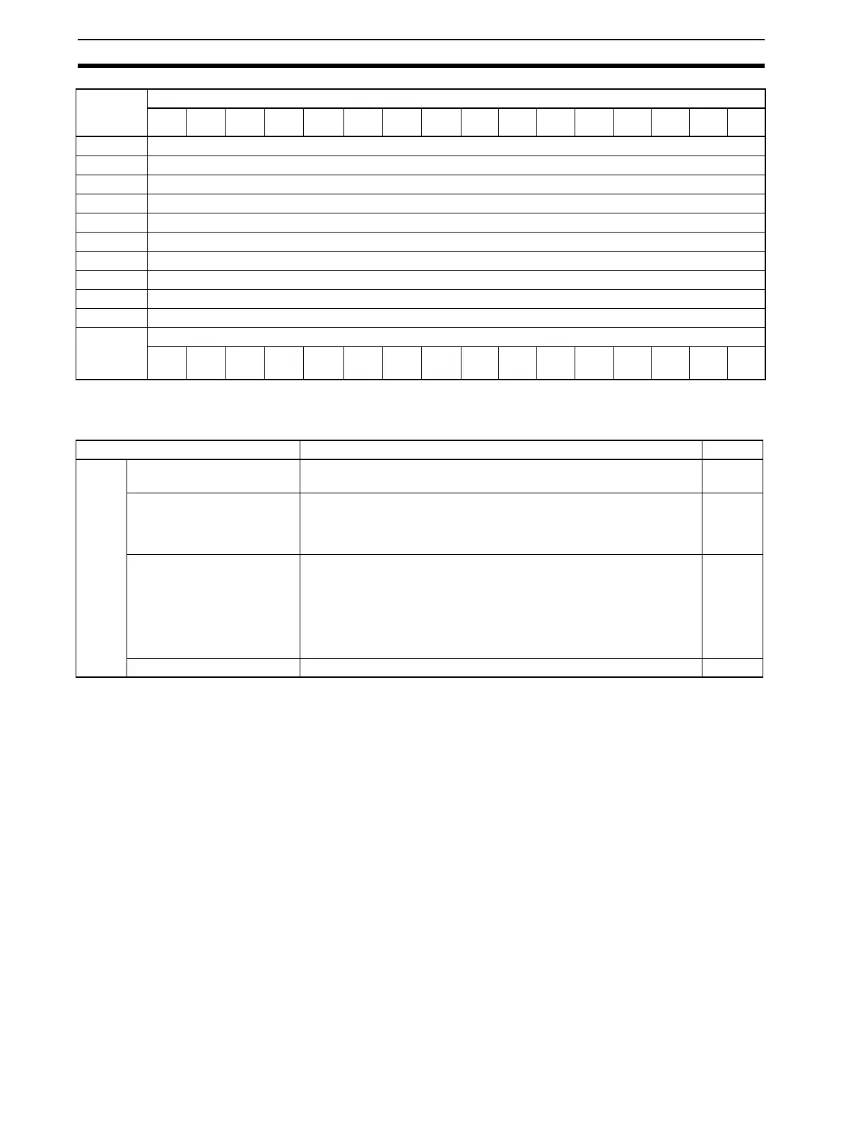
Item Contents Page
Input Use setting 0: Not used.
1: Used.
52
Input signal range 00: –10 to 10 V
01: 0 to 10 V
10: 1 to 5 V/4 to 20 mA (See note 1.)
11: 0 to 5 V
52
Mean value processing set-
ting
0000: Mean value processing for 2 buffers (See note 3.)
0001: No mean value processing
0002: Mean value processing for 4 buffers
0003: Mean value processing for 8 buffers
0004: Mean value processing for 16 buffers
0005: Mean value processing for 32 buffers
0006: Mean value processing for 64 buffers
55
Scaling setting Only set for CS1W-AD161 60
DM word
(See note
1.)
Bits
1514131211109876543210
 Loading...


