4 Basic Operation
4 - 44
E5@C Digital Temperature Controllers User’s Manual (H174)
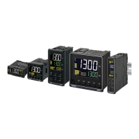
(a) Delta connecting lines: Refer to the following diagram for CT installation
positions.
* Heater voltage fluctuations are not considered, so be sure to take that into account when
setting the detection current.
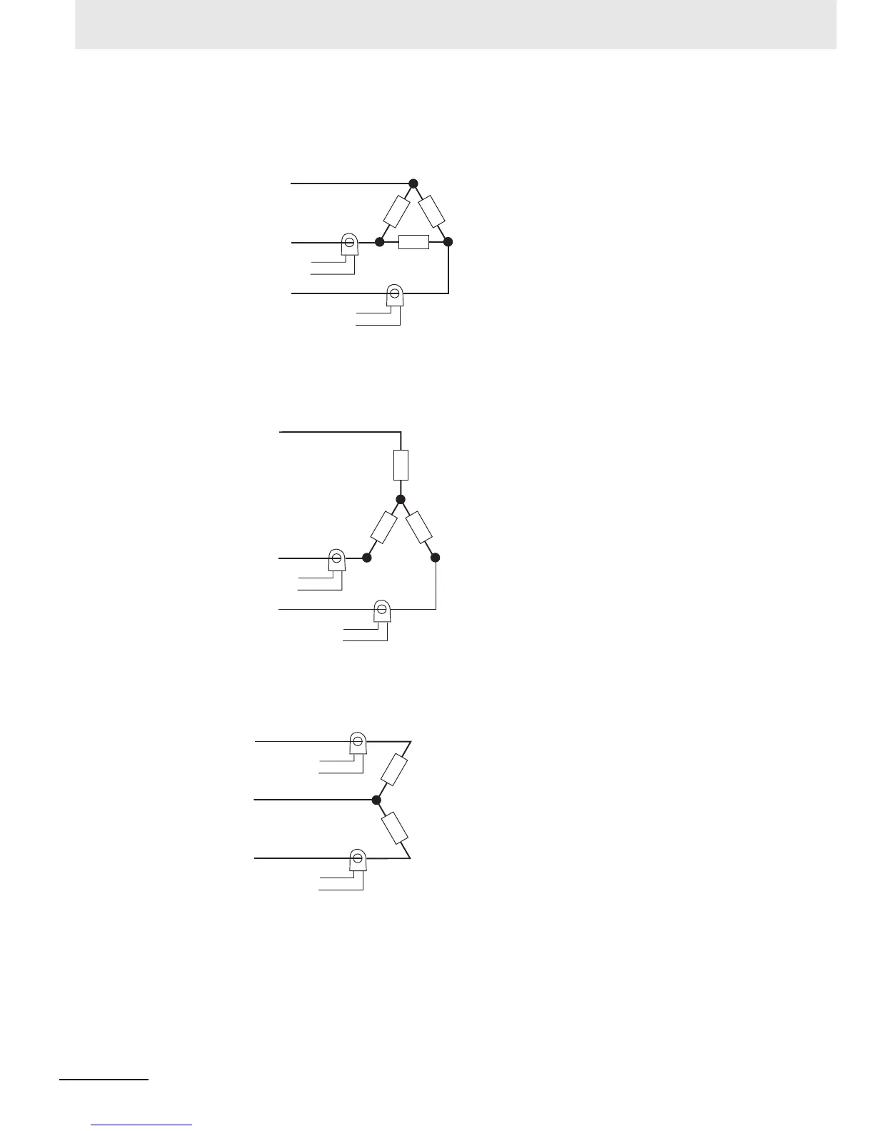
(b) Star connecting lines: Refer to the following diagram for CT installation
positions.
* Heater voltage fluctuations are not considered, so be sure to take that into account when
setting the detection current.
(c) V connecting lines: Refer to the following diagram for CT installation positions.
* Heater voltage fluctuations are not considered, so be sure to take that into account when
setting the detection current.
CT
CT
Load
Load
To CT input
Load
Load (such as a heater)
AC line
AC line
Product
To CT input
Product
CT
CT
Load
Load
Load
Load (such as a heater)
AC line
Product
To CT input
Product
To CT input
CT
Load (such as a heater)
CT
Load
Load
AC line
Product
To CT input
Product
To CT input