6 - 41
6 Parameters
E5@C Digital Temperature Controllers User’s Manual (H174)
6-7 Initial Setting Level
6
6-7 Initial Setting Level
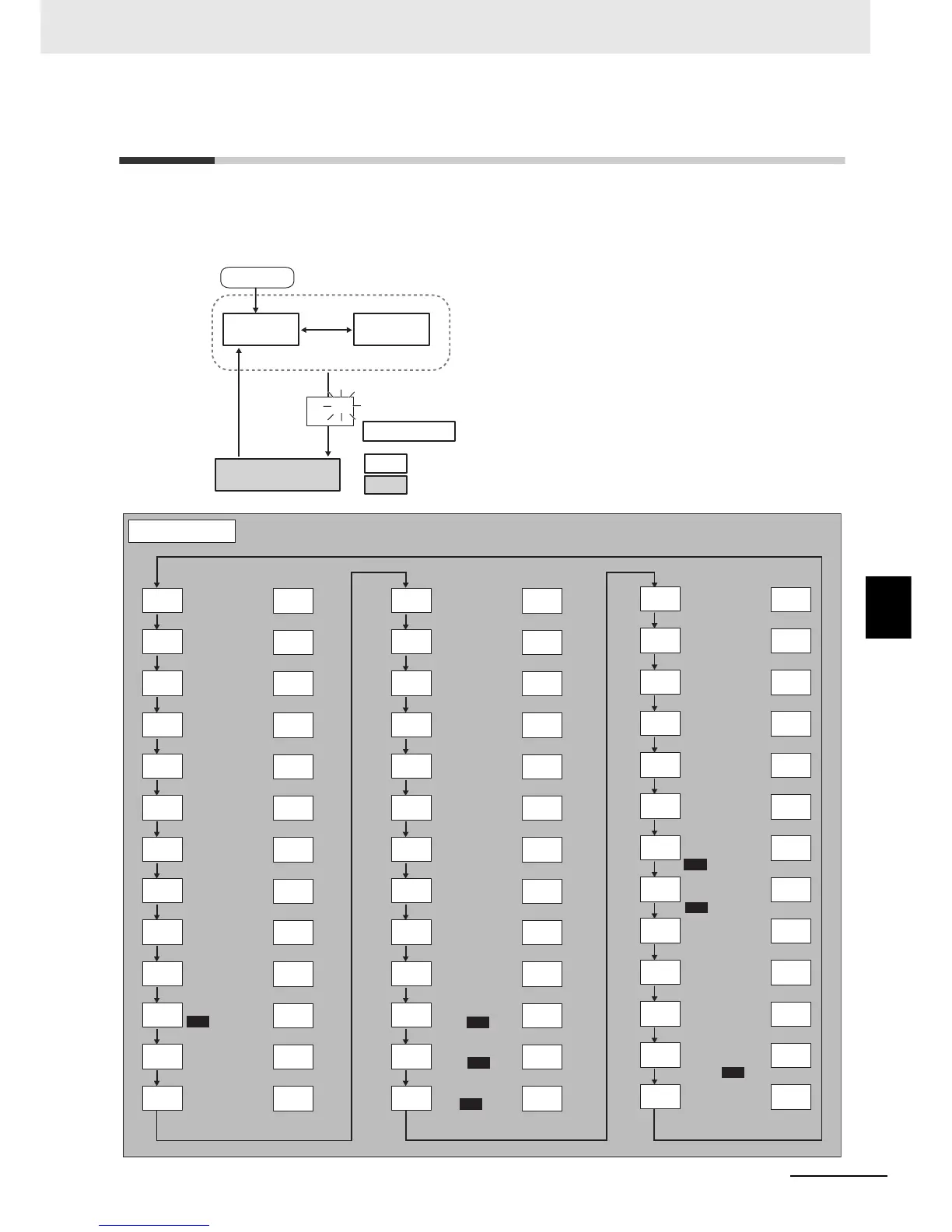
This level is used to set up the basic Digital Controller specifications. In this level, you can set the Input
Type parameter to set the sensor input to be connected, limit the setting range of set points, set the
alarm modes, and perform other operations.
To move from the Operation Level or Adjustment
Level to the Initial Setting Level, press the O Key for
at least three seconds with any parameter displayed
except for the Auto/Manual Switch parameter.
• The Initial Setting Level is not displayed when the
Initial Setting/Communications Protect parameter
is set to 2. It can be used when the Initial
Setting/Communications Protect parameter is set
to 0 or 1.
• If the Input Type parameter is set for an analog
input, the following parameters will be set: Scaling
upper limit, Scaling lower limit, and Decimal point.
Power ON
25
100
Operation
Level
Initial Setting
Level
Control stops.
Control in progress
Control stopped
Press the O Key
for at least 3 s.
Press the
O Key
for at
least 1 s.
Adjustment
Level
Press the O
Key for at
least 1 s;
display will
flash.
Press the
O
Key
less than 1 s.
M
20
cp
M
s
in-t
M
100
in-h
M
0
in-l
M
0
dp
M
c
d-u
M
1300
sl-h
M
-200
sl-l
M
onof
cntl
M
stnd
s-hc
M
on
st
M
off
ptrn
M
M
or-r
orev
M
2
alt1
M
0.2
alh1
M
2
alt2
M
0.2
alh2
M
2
alt3
M
0.2
alh3
M
2
alt4
M
0.2
alh4
M
4-20
o1st
M
4-20
o2st
M
M
M
1300
o1th
M
-200
o1tl
M
msp0
ev-1
M
stop
ev-2
M
none
ev-3
M
none
ev-4
M
none
ev-5
M
none
ev-6
M
flot
clfl
M
off
calb
M
20
c-cp
M
off
tr-t
4-20
trst
M
30
mot
off
sqr
0
amov
Move to Advanced
Function Setting
Level
ST
Event Input
Assignment 1
Event Input
Assignment 2
Event Input
Assignment 3
Event Input
Assignment 4
Event Input
Assignment 5
Event Input
Assignment 6
Initial Setting Level
Page
Page
Input Type
Scaling Upper
Limit
Scaling Lower
Limit
Decimal Point
Temperature Unit
SP Upper Limit
SP Lower Limit
PID·ON/OFF
Program Pattern
Control
Period (Heating)
Control Period
(Cooling)
Direct/Reverse
Operation
Alarm 1 Type
Alarm 2 Type
Alarm 3 Type
Transfer Output
Type
Simple Transfer
Output 1 Upper
Limit
Simple Transfer
Output 1 Lower
Limit
Standard or
Heating/Cooling
Alarm 1
Hysteresis
Alarm 2
Hysteresis
Alarm 3
Hysteresis
Extraction of
Square Root
Enable
Page
Alarm 4 Type
Alarm 4
Hysteresis
Control Output 1
Signal
Control Output 2
Signal
Transfer Output
Signal
Close/Floating
Motor Calibration
Travel Time
000
000
000
000
000
000
000
6-42
6-43
6-43
6-43
6-43
6-44
6-44
6-44
6-45
6-45
6-46
6-46
6-46
6-47
6-47
6-51
6-47
6-51
6-47
6-51
6-47
6-51
6-52
6-52
6-53
6-52
6-55
6-55
6-56
6-56
6-56
6-56
6-56
6-56
6-59
6-59
6-58
6-58
6-59