2 Preparations
2 - 34
E5@C Digital Temperature Controllers User’s Manual (H174)
• Separate input leads and power lines in order to prevent external noise.
• Use a shielded, AWG24 to AWG18 (equal to a cross-sectional area of 0.205 to 0.823 mm
2
)
twisted-pair cable. Use a shielded, AWG24 to AWG14 (equal to a cross-sectional area of 0.205 to
2.081 mm
2
) twisted-pair cable for the E5CC-U. The stripping length is 6 to 8 mm for the E5CC, E5EC,
E5AC, or E5DC, 5 to 6 mm for the E5CC-U, 6 to 8 mm for the E5GC with a screw terminal block, and
8 to 12 mm for the E5GC with a screwless clamp terminal block.
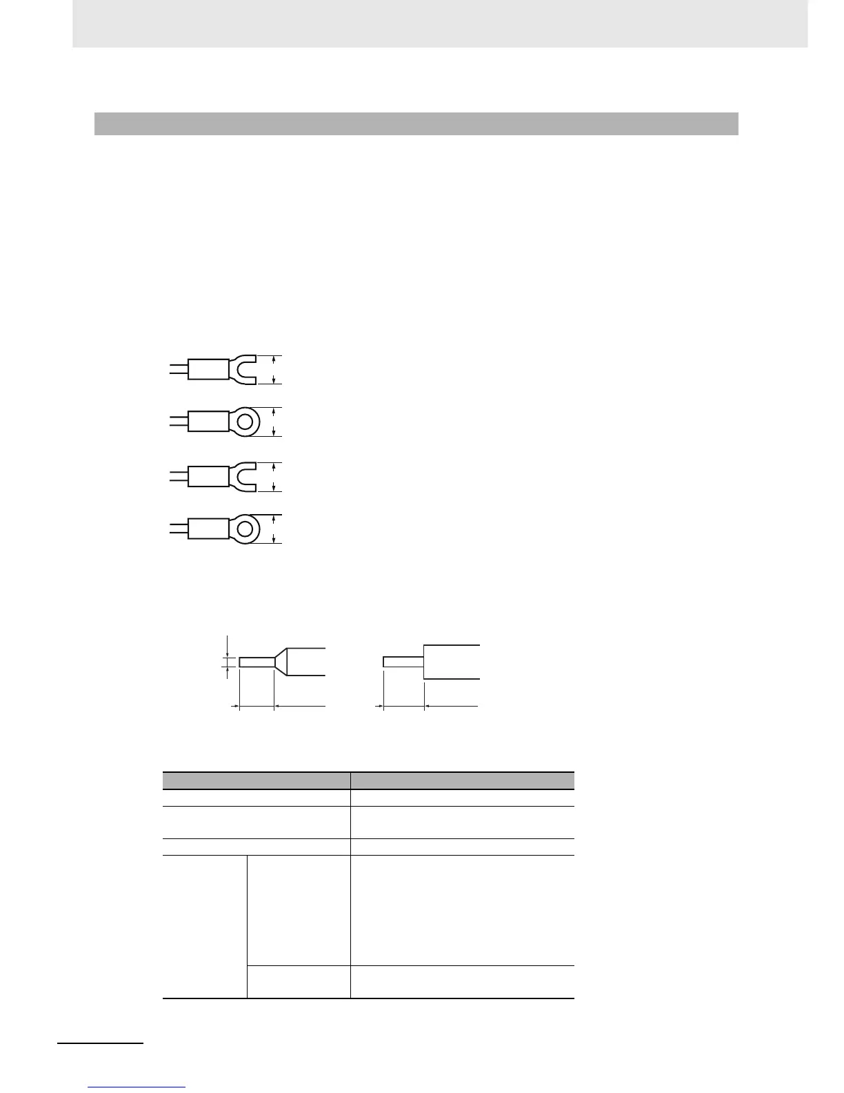
• Use crimp terminals when wiring the terminals.
• Use the suitable wiring material and crimp tools for crimp terminals.
• Tighten the terminal screws to a torque of 0.43 to 0.58 N·m.
• For the E5CC, E5EC, E5AC, or E5DC, or for the E5GC with a screw terminal block, use the following
types of crimp terminals for M3 screws.
For the E5CC-U, use the following types of crimp terminals for M3.5 screws.
For E5GC Digital Controllers with screwless clamp terminal blocks, use braided or solid wires with a
gauge of AWG24 to AWG18 (equal to a cross-sectional area of 0.205 to 0.823 mm
2
).
The length of the conductive portion inserted into the terminal must be 8 to 12 mm. Ferrules must be
0.8 to 1.4 mm in diameter..
Recommended Ferrules for E5GC Screwless Clamp Terminal Blocks
2-2-6 Precautions when Wiring
Manufacturer Model number
Altech Corp. 2623.0
Daido Solderless Terminal Mfg.
Co.
AVA-0.5
J.S.T. Mfg. Co. TUB-0.5
Nichifu Co.,
Ltd.
Single (1 wire) TGNTC-1.25-9T
TGVTC-1.25-11T
TGNTC-1.25-11T
TC0.3-9.5
TC1.25-11S-ST
TC1.25-11S
TC2-11S
Double (2 wires) TGWVTC-1.25-9T
TGWVTC-1.25-11T
5.8 mm max.
5.8 mm max.
7.2 mm ma