7 - 7
7 User Calibration
E5@C Digital Temperature Controllers User’s Manual (H174)
7-4 Resistance Thermometer Calibration
7
7-4 Resistance Thermometer Calibration
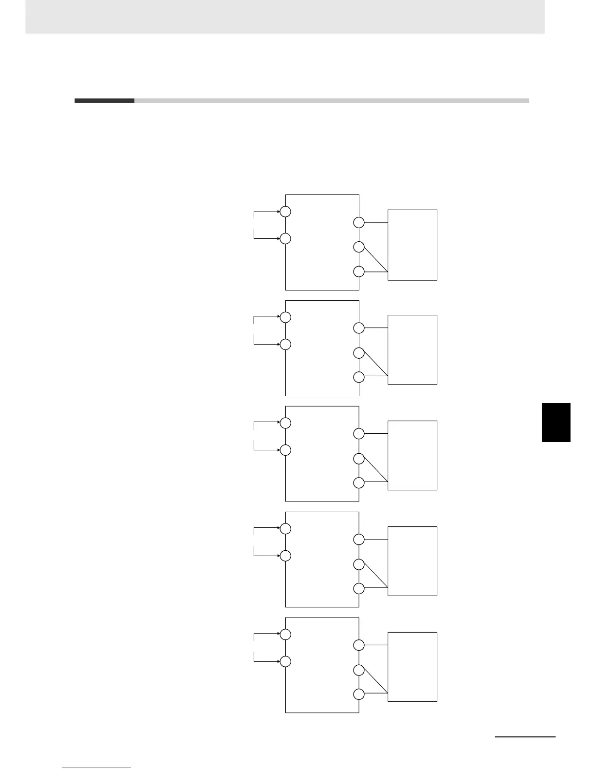
In this example, calibration is shown for Digital Controller with a resistance thermometer set as the input
type. Use connecting wires of the same thickness
1. Connect the power supply.
2. Connect a precision resistance box (called a "6-dial variable resistor" in this manual)
to the resistance thermometer input terminals, as shown in the following diagram.
6-dial variable
resistor
Input power supply
A
4
5
B'
B
6
11
12
E5CC
A
3
2
B'
B
1
10
11
E5CC-U
A
22
23
B'
B
24
1
2
E5EC/AC
A
12
13
B'
B
14
1
2
E5DC
A
10
11
B'
B
12
1
2
E5GC
6-dial variable
resistor
6-dial variable
resistor
6-dial variable
resistor
6-dial variable
resistor
Input power supply
Input power supply
Input power supply
Input power supply
 Loading...