7 User Calibration
7 - 10
E5@C Digital Temperature Controllers User’s Manual (H174)
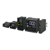
z Calibrating a Voltage Input
In this example, calibration is shown for a Digital Controller with an analog input, with a voltage input
set as the input type.
1. Connect the power supply.
2. Connect an STV and DMM to the voltage input terminals, as shown in the following
diagram.
3. Turn the power ON.
4. Move to the Calibration Level.
This starts the 30-minute aging timer. This timer provides an approximate timer for aging.
After 30 minutes have elapsed, the No. 2 display changes to 0. You can advance to the next
step in this procedure even if 0 is not displayed.
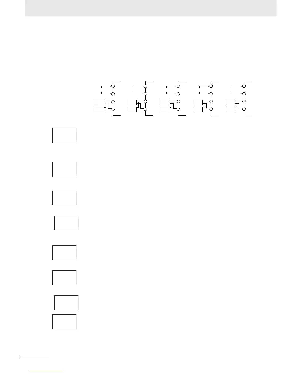
• Input type 27 or
28:
5. When the M Key is pressed, the status changes as shown to the left.
The No. 2 display at this time shows the currently entered count value in hexadecimal. Set
the STV as follows:
• Input type 27 or 28: 5 V
• Input type 29: 10 V
• Input type 30: 54 mV
• Input type 29: Allow the count value on the No. 2 display to fully stabilize, then press the D Key to
temporarily register the calibration settings.
If this count value is outside of the specified range, the No. 2 display will flash and the count
value will not be temporarily registered.
• Input type 30:
• Input type 27 or
28:
6. When the M Key is pressed, the status changes as shown to the left.
Set the STV as follows:
• Input type 27, 28, or 29: 1 V
• Input type 30: −6 mV
• Input type 29: Allow the count value on the No. 2 display to fully stabilize, then press the D Key to
temporarily register the calibration settings.
If this count value is outside of the specified range, the No. 2 display will flash and the count
value will not be temporarily registered.
• Input type 30:
7. When the M Key is pressed, the status changes as shown to the left.
The data to be temporarily registered is not displayed if it is not complete.
Press the U Key. The No. 2 display changes to yes. Release the key and wait two seconds
or press the M Key. This stores the temporarily registered calibration data to non-volatile
memory.
To cancel the saving of temporarily registered calibration data to non-volatile memory, press
the M Key (while no is displayed in the No. 2 display) without pressing the U Key.
Input power
supply
Input power
supply
Input power
supply
Input power
supply
STV
DMM
STV
DMM
E5CC
−
+
E5CC-U
−
+
11
12
5
6
10
11
2
1
STV
DMM
E5EC/AC
−
+
1
2
23
24
STV
DMM
E5DC
−
+
1
2
13
14
STV
DMM
E5GC
−
+
1
2
11
12
Input power
supply
adj
30
1V 5
c7c3
2V10
b104
t 54
b9a5
1V 1
5ac0
2V 1
4ad9
t -6
2988
str
no