2 Preparations
2 - 38
E5@C Digital Temperature Controllers User’s Manual (H174)
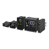
z Control output 1
The following diagrams show the applicable outputs and their internal equivalent circuits.
E5DC
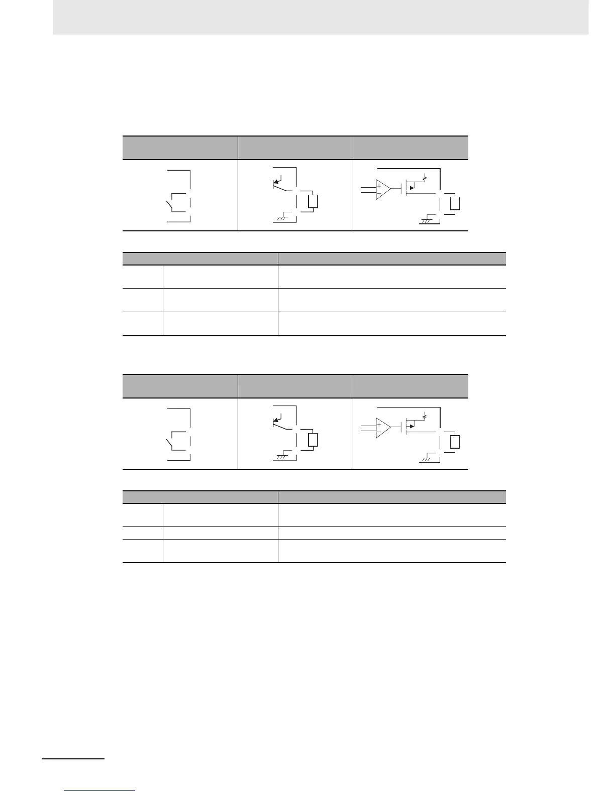
E5GC
z Auxiliary Outputs 1 to 4
• When heating/cooling control is used on the E5CC, E5CC-U, or E5DC and there is only one
control output, auxiliary output 2 is allocated as the control output for cooling. (If the Digital
Controller has only one auxiliary output, an output is not automatically allocated for the control
output for cooling.)
• When heating/cooling control is used on the E5EC or E5AC and there is only one control output,
auxiliary output 4 is allocated as the control output for cooling. (If the Digital Controller has only
two auxiliary outputs, auxiliary output 2 is allocated as the control output for cooling.)
• When heating/cooling control is selected for the E5GC, auxiliary output 1 is assigned as the
control output for cooling.
RX (relay output)
QX (voltage output (for
driving SSR))
CX (linear current output)
Output type Specification
RX Relay output SPST-NO, 250 VAC, 3 A (resistive load), Electrical life:
100,000 operations
QX Voltage output (for driving
SSR)
PNP, 12 VDC ±20%, 21 mA (with short-circuit protection)
CX Linear current output 4 to 20 or 0 to 20 mA DC, Load: 500 Ω max., Resolution:
Approx. 10,000
RX (relay output)
QX (voltage output (for
driving SSR))
CX (linear current)
Output type Specification
RX Relay SPST-NO, 250 VAC, 2 A (resistive load), Electrical
durability: 100,000 operations
QX Voltage (for driving SSR) PNP, 12 VDC ±20%, 21 mA (with short-circuit protection)
CX Linear current 4 to 20 mA DC or 0 to 20 mA DC with load of 500 Ω max.
Resolution: Approx. 10,000
E
F
E
F
+v
+
−
L
E
F
+v
+
−
L
C
D
C
D
+v
+
−
L
C
D
+v
+
−
L