7 User Calibration
7 - 12
E5@C Digital Temperature Controllers User’s Manual (H174)
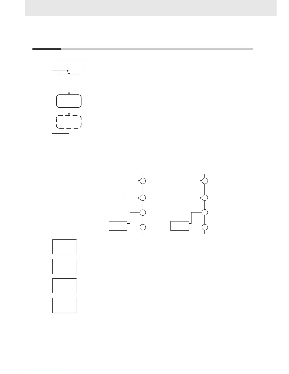
7-6 Calibrating the Transfer Output
For Digital Controllers that have a transfer output, the trans-
fer output calibration display will be displayed after input cal-
ibration has been completed.
The E5CC-U, E5DC, and E5GC do not have a transfer out-
put.
Use the following procedure to calibrate the transfer output for 4 to 20 mA.
1. Connect a DMM to the transfer output terminals.
2. Press the M Key to display the parameter for the transfer output.
3. The calibration display for 20 mA will be displayed. Press the U or D Key until
the DMM monitor value changes to 20 mA.
Press the M Key. The calibration settings will be temporarily registered.
4. The calibration display for 4 mA will be displayed. Press the U or D Key until the
DMM monitor value changes to 4 mA.
Press the M Key. The calibration settings will be temporarily registered.
5. To cancel saving the temporarily registered calibration data to non-volatile
memory, press the M Key without pressing the U Key, i.e., while no is displayed
in the No. 2 display.
Press the U Key. The No. 2 display changes to yes. Release the key and wait 2
seconds or press the M Key. This saves the temporarily registered calibration data
in non-volatile memory.
6. The Calibration Mode is ended by turning OFF the power supply.
Advanced Function
Setting Level
Transfer Output
Calibration
Main Input
Calibration
Input calibration
display
adj
30
M
M
M
M
Note: This is displayed only
for Digital Controllers
that have a transfer
output.
Input power supply
DMM
E5CC
+
−
Input power supply
DMM
E5EC/E5AC
+
−
11
12
17
18
1
2
32
33
str
no
a20.t
52ac
a4.t
0037
str.t
no