1 - 5
1 Introduction
E5@C Digital Temperature Controllers User’s Manual (H174)
1-2 I/O Configuration and Model
Number Legend
1
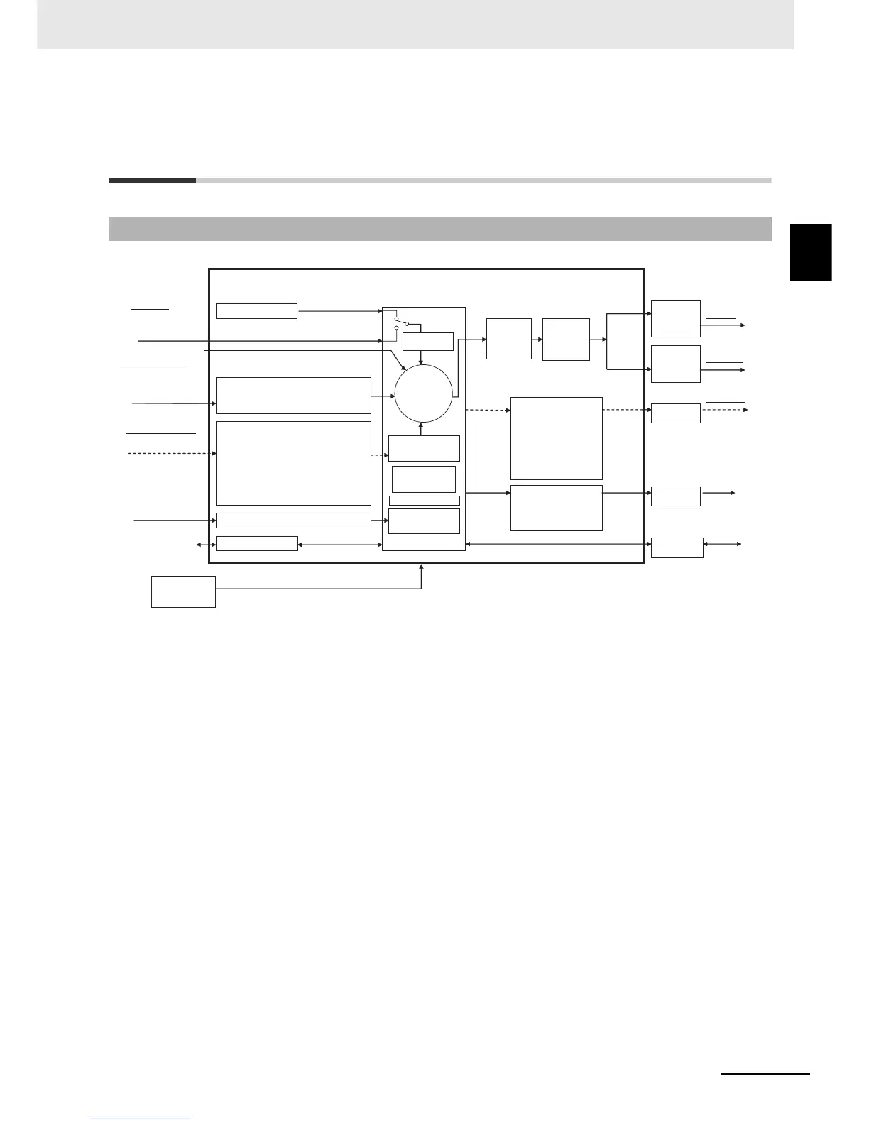
1-2-1 I/O Configuration
1-2 I/O Configuration and Model Number
Legend
Note: Not all models support these functions. For details, refer to 1-2-2 Model Number Legends.
1-2-1 I/O Configuration
E5@C
Auxiliary outputs 1 to 4
• Input type • Input shift
• Input filter • Moving average
• Extraction of square root • Analog scaling
Input signals
Event inputs (EV1 to EV6)
• External inputs
(contact or non-contact input)
Setting and monitoring
• Direct/reverse
• Auto/manual
• Linear current
• Voltage output
(for driving SSR)
• Relay
Outputs
• RS-485
PV
•
Standard alarms (alarms 1 to 4)
• HB alarm
• HS alarm
• Input error (S.ERR)
•
RSP input error
•
Integrated alarm
•
RUN status
•
Program end
•
Work bits 1 to 8
Manipulated
value
(MV)
Setup Tool (CX-Thermo)
Limits
Output signals
A: 100 to 240 VAC
or
D: 24 VAC/DC
• CompoWay/F
• Modbus-RTU
Communications
• Linear current
• Linear voltage
Transfer output
CT input
Multi-SP
Input voltage from CT
Inputs
Set point (SP)
Local SP
Analog input (current/voltage)
Control
• HB alarm
• HS alarm
Alarms
Power supply
• Set point
• Set point during SP ramp
• Process value
• Manipulated value
• Relay
Analog status
Control output 1
Contact status
Operation
Process value (PV) input
• Thermocouple
• Resistance thermometer
• Infrared Temperature Sensor
• Analog input (current/voltage)
• Linear current
• Voltage output
(for driving SSR)
• Relay
Control output 2
• PID or
• ON/OFF control
Cooling
Close
*
*
*
Remote SP
SP mode
SP
• RUN/STOP switching •
Auto/manual selection
• Program start
•
100% AT execute/cancel
• 40% AT execute/cancel
• Alarm latch cancel • Multi-SP No.
• SP ramp
• Set point limiter
• Invert direct/reverse
operation
• SP mode
(remote/local
switching)
• Setting change
enable/disable
• Communications
write enable/disable
• Standard control or
• Heating/cooling
control
Automatic setting of
PID constants with AT
or ST
• MV limit
• MV
rate-of-
change limit
*
Functions can be assigned individually for each output by
changing the set values for the Control Output 1 and 2
Assignments and the Auxiliary Output 1 to 4 Assignments in the
parameters in the advanced function setting level.
Potentiometer input
Heating
Open
FB