5 - 63
5 Advanced Operations
E5@C Digital Temperature Controllers User’s Manual (H174)
5-21 Controlling Valves (Can Be Used with a Position-proportional Model)
5
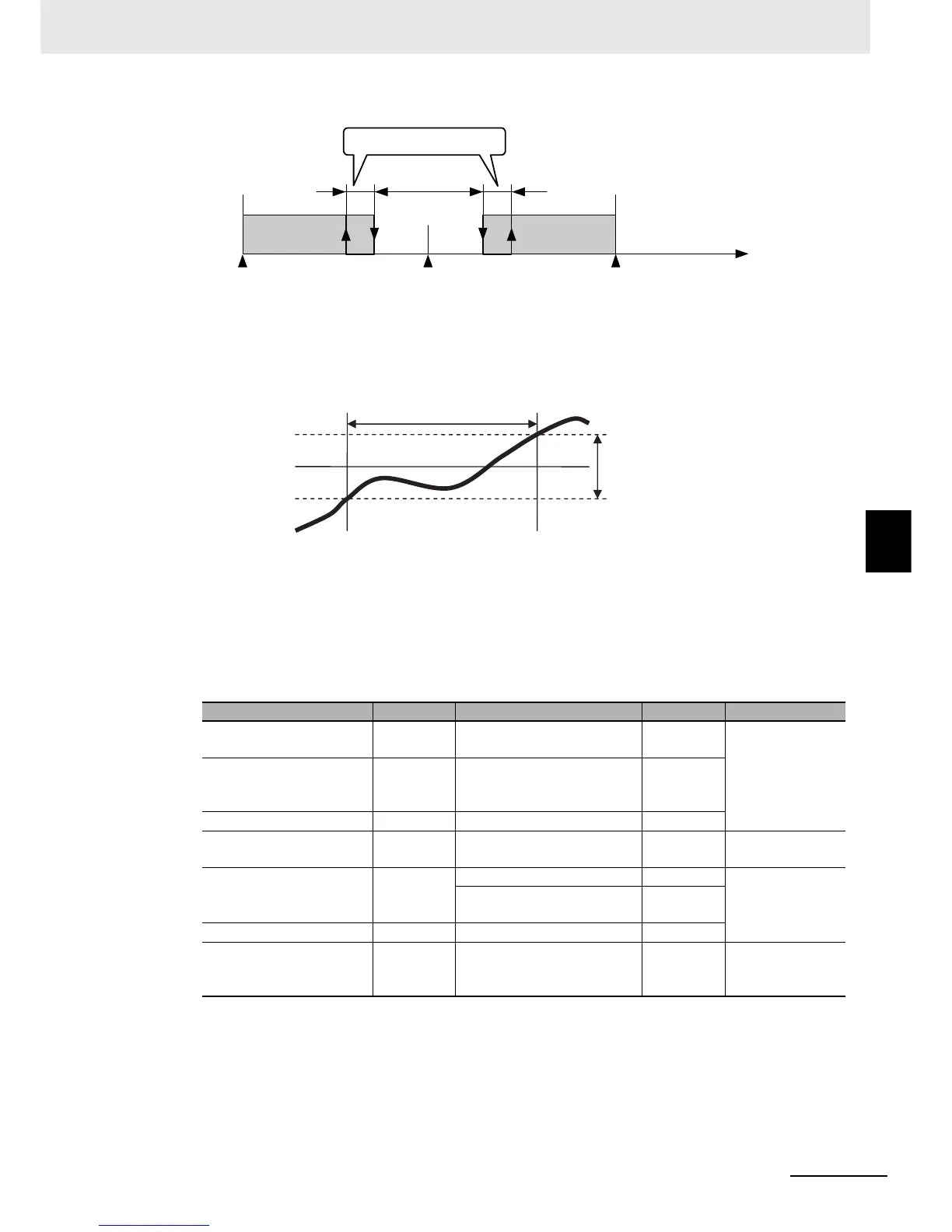
z PV Dead Band
When the PV enters the PV dead band, any unnecessary output is stopped to prevent the valve
from deteriorating.
z Manual MV, MV at Stop, and MV at PV Error
Refer to the following sections.
Manual PV: 5-12-1 Manual MV
MV at Stop and MV at PV Error: 5-15 Output Adjustment Functions
z Related Displays and Parameters
* Motor calibration not performed, potentiometer not connected, or potentiometer input error.
Parameter name Display Set (monitor) values Default Level
Close/Floating
clfl FLOT: Floating control
CLOS: Close control
FLOT
Initial Setting
LevelMotor Calibration
calb OFF
ON
ERR (Error occurred.)
OFF
Trave l T i me mot 0 to 999 (s) 30
Valve Opening Monitor
V-m Normal: −10.0% to 110.0%
Error: ----*
---
Operation Level
Position Proportional Dead
Band
db Close control: 0.1% to 10.0% 4.0
Adjustment Level
Floating control: 0.1% to
10.0%
2.0
Open/Close Hysteresis oc-h 0.1 to 20.0 0.8
PV Dead Band
p-db
0 to 9999
0.0 Advanced
Function Setting
Level
0
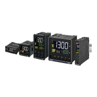
Position Proportional
Dead Band
−100%
OFF
ON
100%
MV − Valve opening
Open/Close Hysteresis
SP
PV
Unnecessary output is
stopped in this range.
PV Dead Band
 Loading...