3 - 17
3 Part Names and Basic Procedures
Digital Temperature Controllers (Simple Type) User’s Manual (H211)
3-4 Procedures after Turning ON the Power Supply
3
3-4-2 Basic Procedure
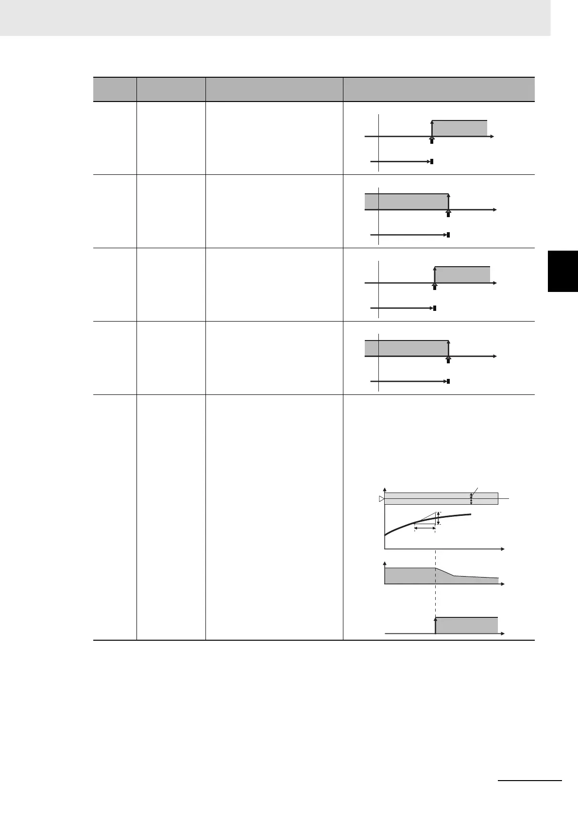
8 Absolute-value
upper-limit
alarm
The alarm output is ON while the
PV is equal to or higher than the
alarm value.
9 Absolute-value
lower-limit
alarm
The alarm output is ON while the
PV is equal to or lower than the
alarm value.
10 Absolute-value
upper-limit
alarm with
standby
sequence
This alarm provides a standby
sequence.
The alarm output is ON while the
PV is equal to or higher than the
alarm value.
11 Absolute-value
lower-limit
alarm with
standby
sequence
This alarm provides a standby
sequence.
The alarm output is ON while the
PV is equal to or lower than the
alarm value.
12 Loop Burnout
Alarm (LBA)
(Valid only for
alarm 1.)
The alarm output turns ON when
the control loop is broken.
There is assumed to be a loop burnout alarm if
the control deviation (SP − PV) is greater than
the threshold set in the LBA Level parameter
and if the PV is not reduced by at least the
value set in the LBA Band parameter within a
specific period of time. The LBA detection time
and LBA band are set in parameters.
Alarm
type No.
Alarm type Description Operation
ON
OFF
0
Temperature
Upper-limit alarm
point (e.g., 100°C)
Alarm value (e.g., 100°C)
Example:
ON
OFF
0
Temperature
Lower-limit alarm
point (e.g., 100°C)
Example:
Alarm value (e.g., 100°C)
ON
OFF
0
Temperature
Upper-limit alarm
point (e.g., 100°C)
Alarm value (e.g., 100°C)
Example:
ON
OFF
0
Temperature
Lower-limit alarm
point (e.g., 100°C)
Example:
Alarm value (e.g., 100°C)
ON
SP
MV
LBA Alarm Output
PV
100%
0%
OFF Time
Time
Time
LBA detection time
LBA band
LBA level