A - 3
A Appendices
Digital Temperature Controllers (Simple Type) User’s Manual (H211)
A-1 Specifications
A
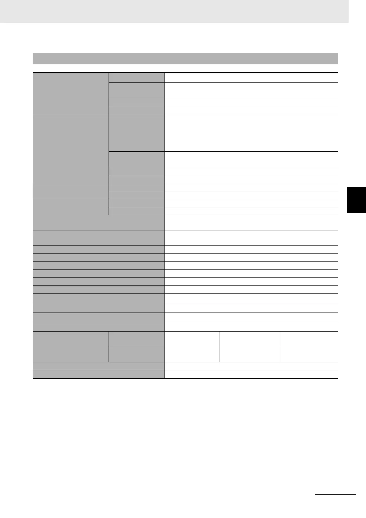
A-1-2 Characteristics
*1 The indication accuracy of K, T, and N thermocouples at a temperature of −100°C or less is ±2°C ±1 digit maximum.
The indication accuracy of U and L thermocouples is ±2°C ±1 digit maximum.
The indication accuracy of B thermocouples at a temperature of 400°C or less is not specified.
The indication accuracy of B thermocouples at a temperature of 400 to 800°C is ±3°C maximum.
The indication accuracy of R and S thermocouples at a temperature of 200°C or less is ±3°C ±1 digit maximum.
The indication accuracy of W thermocouples is (±0.3% of PV or ±3°C, whichever is greater) ±1 digit maximum.
The indication accuracy of PLII thermocouples is (±0.3% of PV or ±2°C, whichever is greater) ±1 digit maximum.
*2 Ambient temperature: −10°C to 23°C to 55°C
Voltage range: −15 to +10% of rated voltage
*3 The unit is determined by the setting of the Integral/Derivative Time Unit parameter.
A-1-2 Characteristics
Indication accuracy
(ambient temperature of
23°C)
Thermocouple
*
1
(±0.3% of PV or ±1°C, whichever is greater) ±1 digit max.
Resistance
thermometer
(±0.2% of PV or ±0.8°C, whichever is greater) ±1 digit max.
Analog input ±0.2% FS ±1 digit max.
CT input ±5% FS ±1 digit max.
Temperature variation
influence
*
2
Voltage variation influence
*
2
Thermocouple
Thermocouple (R, S, B, W, PLII)
(±1% of PV or ±10°C, whichever is greater) ±1 digit max.
Other thermocouples:
(±1% of PV or ±4°C, whichever is greater) ±1 digit max.
*K thermocouple at −100°C max: ±10°C max.
Resistance
thermometer
(±1% of PV or ±2°C, whichever is greater) ±1 digit max.
Analog input ±1% FS ±1 digit max.
CT input ±5% FS ±1 digit max.
Hysteresis
Temperature input 0.1 to 999.9°C or °F (in units of 0.1°C or °F)
Analog input 0.01% to 99.99% FS (in units of 0.01% FS)
Proportional band (P)
Temperature input 0.1 to 999.9°C or °F (in units of 0.1°C or °F)
Analog input 0.1% to 999.9% FS (in units of 0.1% FS)
Integral time (I)
*
3
0 to 9,999 s (in units of 1 s)
0.0 to 999.9 s (in units of 0.1 s)
Derivative time (D)
*
3
0 to 9,999 s (in units of 1 s)
0.0 to 999.9 s (in units of 0.1 s)
Control Period 0.1, 0.2, 0.5, or 1 to 99 s (in units of 1 s)
Manual reset value 0.0% to 100.0% (in units of 0.1%)
Alarm setting range −1,999 to 9,999 (decimal point position depends on input type)
Sampling cycle 50 ms
Insulation resistance 20 MΩ min. (at 500 VDC)
Dielectric strength 2,300 VAC, 50/60 Hz for 1 min between terminals of different charge
Malfunction vibration
10 to 55 Hz, 20 m/s
2
for 10 min each in X, Y and Z directions
Vibration resistance
10 to 55 Hz, 20 m/s
2
for 2 hr each in X, Y, and Z directions
Malfunction shock
100 m/s
2
, 3 times each in X, Y, and Z directions
Shock resistance
300 m/s
2
, 3 times each in X, Y, and Z directions
Weight
E5CC
Approx. 120 g Adapter:
Approx. 10 g
Terminal cover:
Approx. 0.5 g each
E5EC
Approx. 210 g Adapter:
Approx. 4 g × 2
Terminal Cover:
Approx. 1 g each
Degree of protection Front panel: IP66, rear case: IP20, terminals: IP00
Memory protection Non-volatile memory (number of writes: 1,000,000)