1 - 5
1 Introduction
Digital Temperature Controllers (Simple Type) User’s Manual (H211)
1-2 I/O Configuration and Model
Number Legend
1
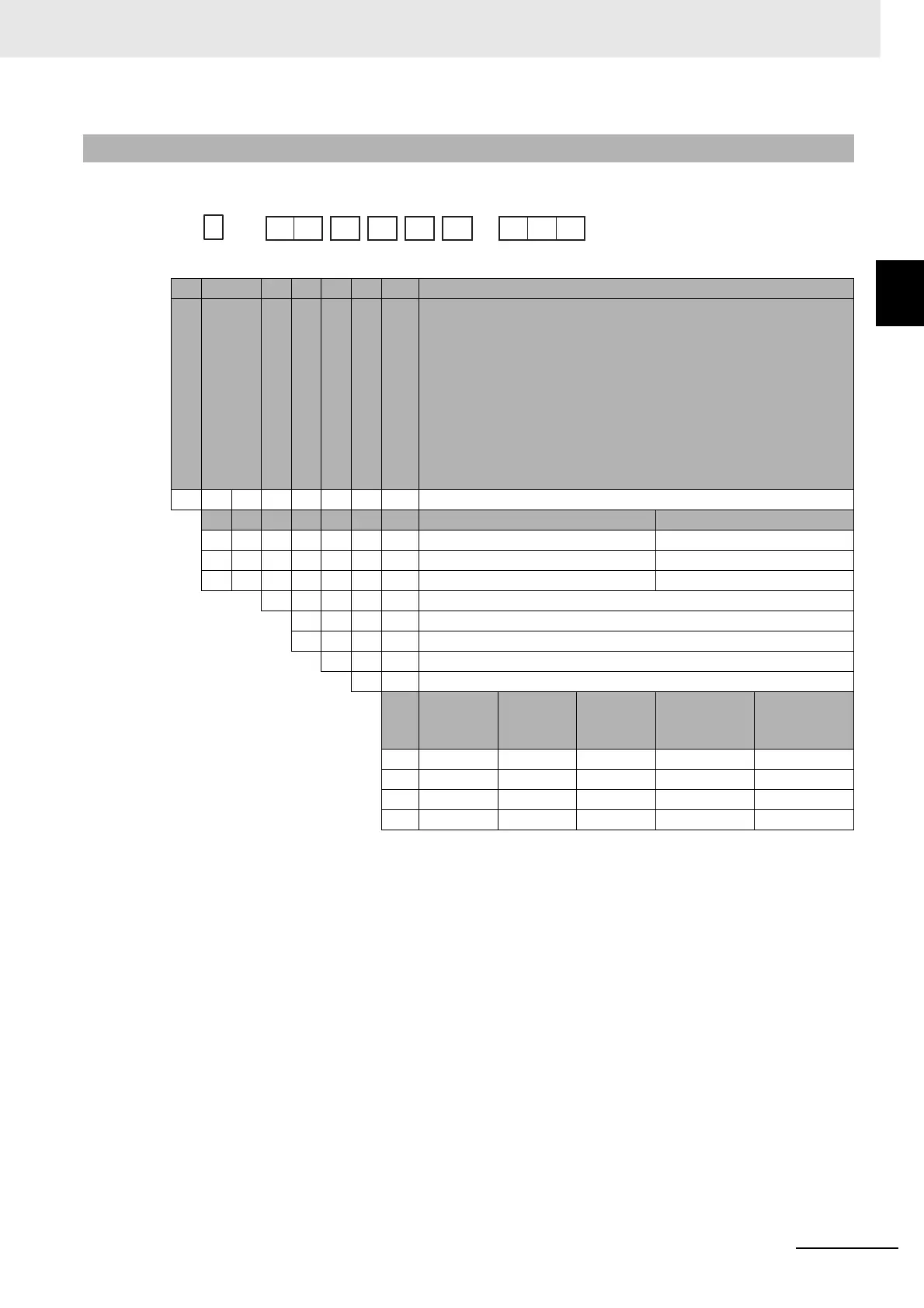
1-2-2 Model Number Legends
z E5CC
* The control output cannot be used as a transfer output.
1-2-2 Model Number Legends
(1) (2) (3) (4) (5) (6) (7) Meaning
C48 × 48 mm
Control output 1 Control output 2
R X Relay output None
Q X Voltage output (for driving SSR) None
* C X Linear current output None
22
A 100 to 240 VAC
D 24 VAC/DC
S Screw terminals
M Universal input
Event
inputs
Communi
cations
HB alarm
and HS
alarm
*For RX or
QX
*For CX
800 --- --- --- Provided. Provided.
801 2 --- 1 Provided. ---
802 --- RS-485 1 Provided. ---
804 2 RS-485 --- --- Provided.
-
-
E5CC
-
-
(1) (2) (3) (4) (5) (6) (7)
2
SM
8
Size
Control Outputs 1 and 2
No. of auxiliary outputs
Power supply voltage
Terminal type
Input type
Options