2 Preparations
2 - 14
Digital Temperature Controllers (Simple Type) User’s Manual (H211)
• Separate input leads and power lines in order to prevent external noise.
• Use a shielded, AWG24 to AWG18 (cross-sectional area of 0.205 to 0.823 mm
2
) twisted-pair cable.
The stripping length is 6 to 8 mm.
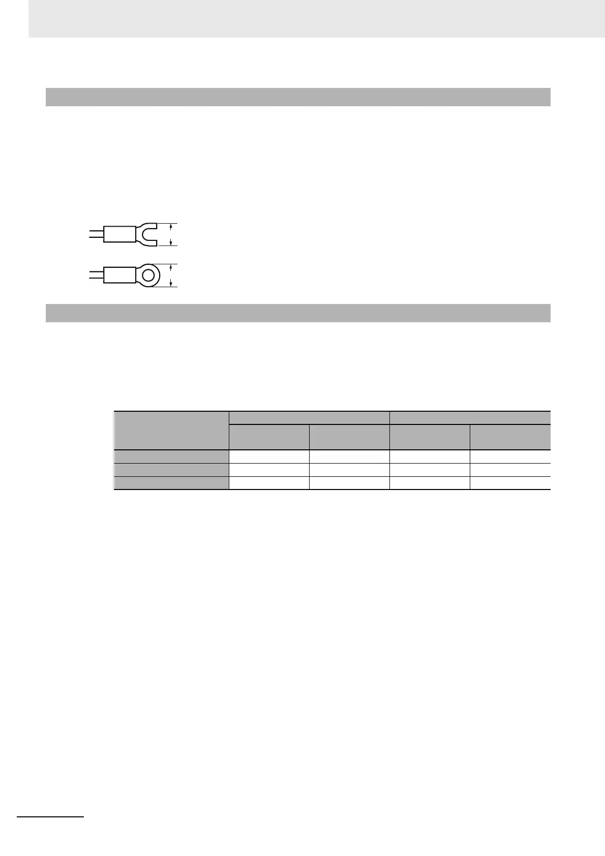
• Use crimp terminals when wiring the terminals.
• Use the suitable wiring material and crimp tools for crimp terminals.
• Tighten the terminal screws to a torque of 0.43 to 0.58 N·m.
• Use the following types of crimp terminals for M3.0 screws.
In the connection diagrams, the left side of the terminal numbers represents the inside of the Controller
and the right side represents the outside.
z Power Supply
Power Consumption
• These models have reinforced insulation between the input power supply, the relay outputs, and
other terminals.
z Inputs
Refer to 2-2-1 E5CC Terminal Block Wiring Example or 2-2-2 E5EC Terminal Block Wiring Example for the
terminal arrangement. When extending the thermocouple lead wires, be sure to use compensating wires that
match the thermocouple type. When extending the lead wires of a resistance thermometer, be sure to use wires
that have low resistance and keep the resistance of the three lead wires the same.
2-2-3 Precautions when Wiring
2-2-4 Wiring
Input Power Supply
E5CC E5EC
Options No.: 800
Options No.:
Not 800
Options No.: 800
Options No.:
Not 800
100 to 240 VAC, 50/60 Hz 5.2 VA max. 6.5 VA max. 6.6 VA max. 8.3 VA max.
24 VAC, 50/60 Hz 3.1 VA max. 4.1 VA max. 4.1 VA max. 5.5 VA max.
24 VDC (no polarity) 1.6 W max. 2.3 W max. 2.3 W max. 3.2 W max.
5.8 mm max.
5.8 mm max.