82
Setting Scaling Upper and Lower Limits for Analog Inputs Section 4-3
• Use an event input.
For details on setting the PF Key, refer to 4-19 Setting the PF Key. For details
on setting events, refer to 4-5 Using Event Inputs.
Summary of Alarm
Operation
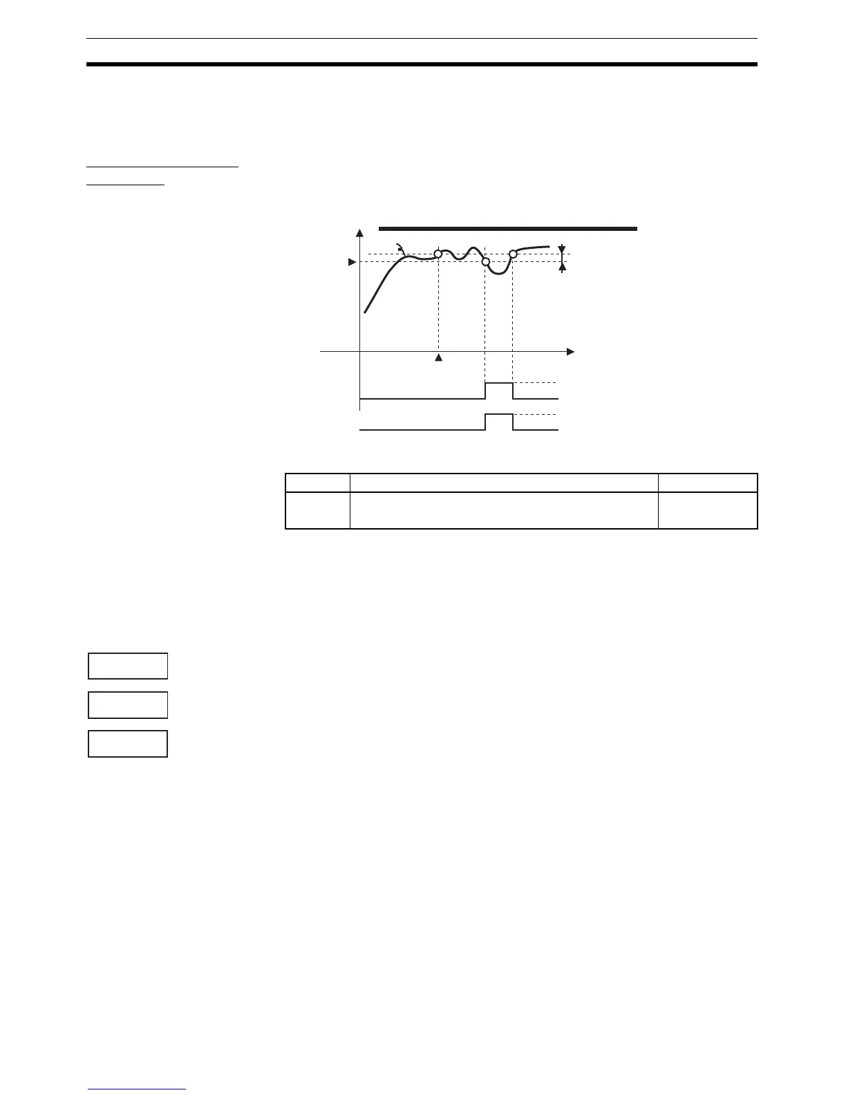
The following figure summarizes the operation of alarms when the Alarm Type
parameter is set to “lower-limit alarm with standby sequence” and “close in
alarm” is set.
Parameters
Note * = 1 to 3
4-3 Setting Scaling Upper and Lower Limits for Analog Inputs
4-3-1 Analog Input
• When an analog input is selected, scaling can be performed as needed
by the control application.
• Scaling is set in the Scaling Upper Limit, Scaling Lower Limit, and Deci-
mal Point parameters (initial setting level). These parameters cannot be
used when a temperature input is selected.
• The Scaling Upper Limit parameter sets the physical quantity to be
expressed by the upper limit value of input, and the Scaling Lower Limit
parameter sets the physical quantity to be expressed by the lower-limit
value of input. The Decimal Point parameter specifies the number of digits
below the decimal point.
• The following figure shows a scaling example for a 4 to 20 mV input.
After scaling, the humidity can be directly read. Here, one place below the
decimal point is set.
OFF
ON
PV
Alarm type: Lower-limit alarm with standby sequence
Alarm value
Alarm hysteresis
Time
Standby sequence
canceled
Alarm
Output
OFF
ON (closed)
Symbol Parameter: level Description
alh*
rest
Alarm 1 to 3 Hysteresis: Initial setting level
Standby Sequence: Advanced function setting level
Alarm
Alarm
in-h
in-l
dp
Scaling Upper Limit
Scaling Lower Limit
Decimal Point