122
Using the Extraction of Square Root Parameter Section 4-17
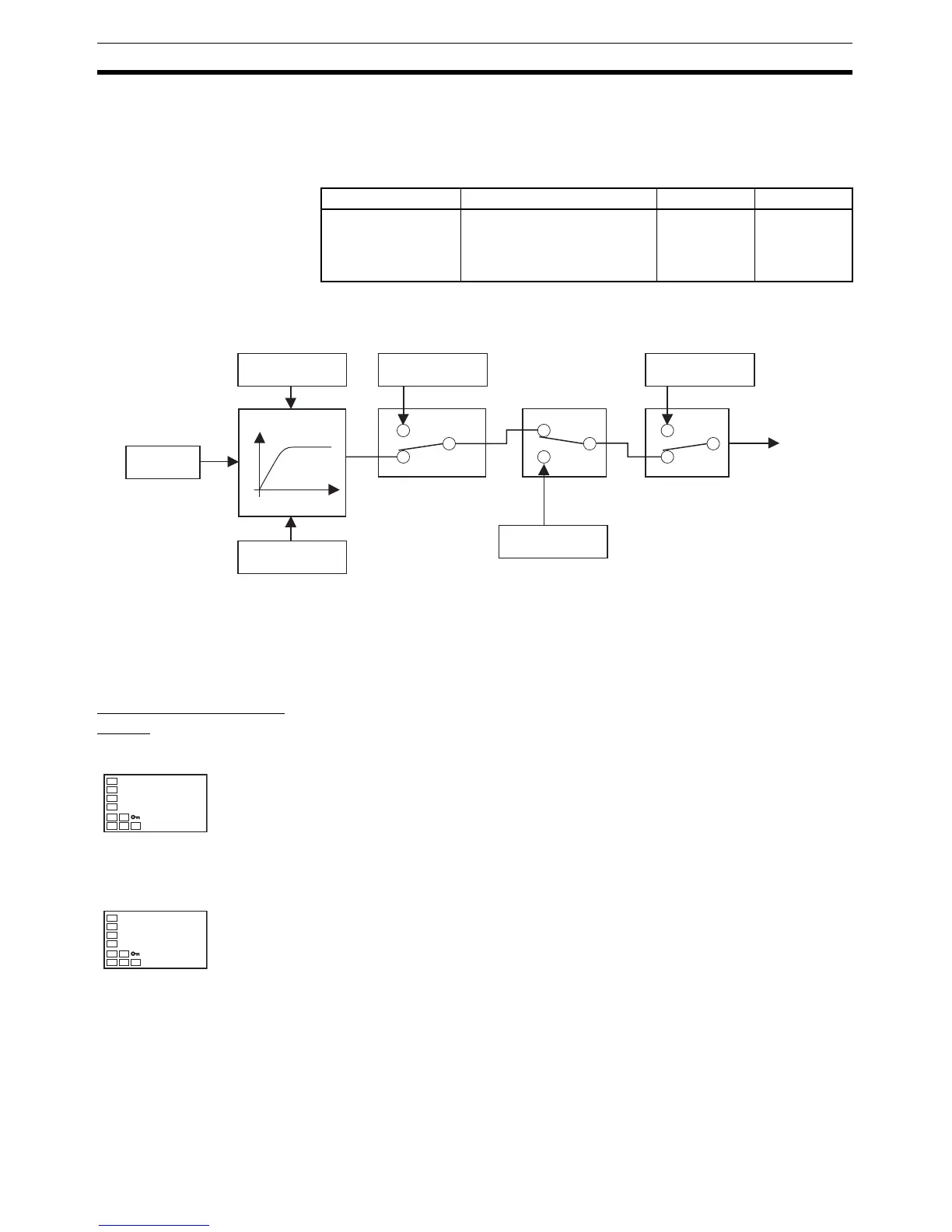
4-16-3 MV at PV Error
• The MV to be output for input errors can be set.
The MV at stop takes priority when stopped and the manual MV takes pri-
ority in manual mode.
Note The order of priority is as follows: Manual MV > MV at stop > MV at PV error.
• The order of priority of the MVs is illustrated in the following diagram.
Note When the Manual MV Limit Enable parameter is set to ON, the setting range
will be the MV lower limit to the MV upper limit.
4-17 Using the Extraction of Square Root Parameter
Extraction of Square
Roots
Parameter name Setting range Unit Default
MV at PV ERROR −5.0 to 105.0 for standard
control
−105.0 to 105.0 (heating/cool-
ing control)
%0.0
PID
calculations
MV upper limit
Manipulated variable
Time
MV lower limit
MV at PV Error
Input error
RUN/STOP
MV at Stop
Manual MV
(See note.)
Auto/manual switch
Output
Extraction of Square Root Enable
• For analog inputs, the Extraction of Square Root parameter is provided
for inputs so that differential pressure-type flow meter signals can be
directly input.
• The default setting for the Extraction of Square Root parameter is OFF.
The Extraction of Square Root Enable parameter must be set to ON in
order to use this function.
Extraction of Square Root Low-cut
Point
• If the PV input (i.e., the input before extracting the square root) is higher
than 0.0% and lower than the low cut point set in the Extraction of
Square Root Low-Cut Point parameter, the results of extracting the
square root will be 0.0%. If the PV input is lower than 0.0% or higher
than 100.0%, extraction of the square root will not be executed, so the
result will be equal to the PV input. The low-cut point is set as normal-
ized data for each input, with 0.0 as the lower limit and 100.0 as the
upper limit for the input setting range.
sqr
off
sqrp
0.0