26
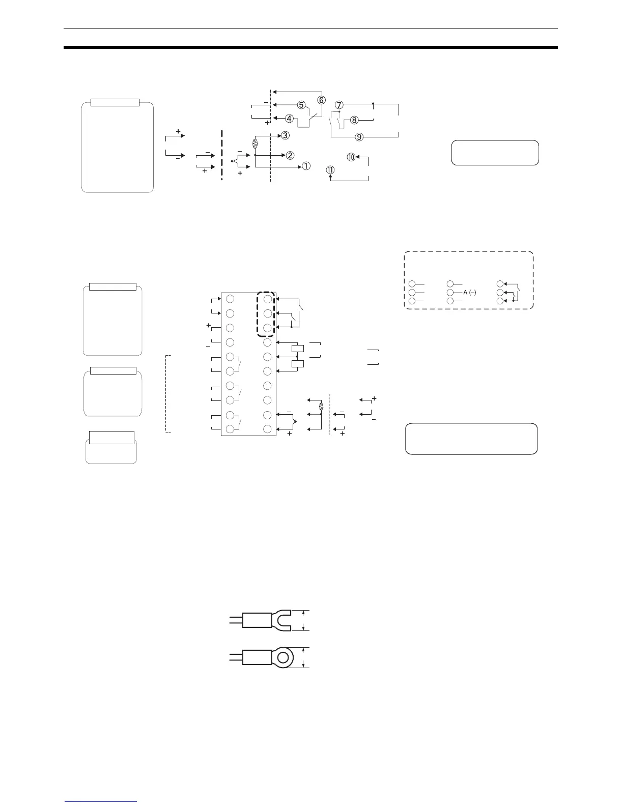
Wiring Terminals Section 2-2
E5CN-U
Note For the Wiring Socket, purchase the P2CF-11 or PG3A-11 separately.
E5AN/EN
Controllers Option Units
2-2-2 Precautions when Wiring
• Separate input leads and power lines in order to prevent external noise.
• Use AWG24 (cross-sectional area: 0.205 mm
2
) to AWG14 (cross-sec-
tional area: 2.081 mm
2
) twisted-pair cable (stripping length: 5 to 6 mm).
• Use crimp terminals when wiring the terminals.
• Tighten the terminal screws to a torque of 0.74 to 0.90 N·m, except for the
E5CN-U, which is 0.5 N·m.
• Use the following types of crimp terminals for M3.5 screws.
Note Do not remove the terminal block. Doing so will result in malfunction or failure.
A
B
B
Auxiliary output
250 VAC, 3 A (resistive load)
Control output 1
TC/Pt
universal input
Input power supply
• 100 to 240 VAC
• 24 VAC/VDC (no polarity)
Auxiliary output 1
(Relay outputs)
DO NO T
USE
Analog input
V
mA
DO NO T
USE
DO NO T
USE
An input error is sent to the
sent to which the alarm 1
function is assigned.
Current output
0 to 20 mA DC
Relay output
(three terminals used)
SPDT, 250 VAC, 3 A
(resistive load)
Voltage output
(for driving SSR)
12 VDC, 21 mA
Load: 600 Ω max.
4 to 20 mA DC
Control output 1
Auxiliary output 2
(Control output (cooling side))
Input power supply
Auxiliary output 2
1
2
3
4
5
13
14
15
6
7
8
9
10
16
17
18
19
Control output 1
Analog input
TC/Pt universal input
B
V
mA
Auxiliary output 3
20
CT1
CT2
EV1
EV2
CT1/CT2 Control Output 2
+
-
Control output 2
DO NOT
USE
+
-
External power supply
12 VDC, 20 mA
DO NOT
USE
External Power Supply
DO NOT
USE
B
A
DO NOT
USE
DO NOT
USE
DO NOT
USE
Auxiliary output 1
Event Inputs
11
12
A heater burnout alarm, heater short alarm,
heater overcurrent alarm, or input alarm is
sent to the output to which the alarm 1
function is assigned.
250 VAC, 3 A
(resistive load)
Relay outputs
Auxiliary output
1, 2, 3
• 100 to 240 VAC
• 24 VAC/VDC (no polarity)
Current output
0 to 20 mA DC
Voltage output
(for driving SSR)
12 VDC, 40 mA
Load: 600 Ω max.
4 to 20 mA DC
Relay output
250 VAC, 5A
(resistive load)
Control output 2
Voltage output
(for driving SSR)
12 VDC, 21 mA
Control output 1
Long-life relay output
250 VAC, 3 A
(resistive load)
Communications
E53-EN03
RS-485
B (+)11
12
DO NOT USE13
E53-EN01
RS-232C
SD11
RD12
SG13
E53-AKB
Event inputs
11
12
13
EV
EV2
CT1/CT2
7.2 mm max.
7.2 mm max.