27
Wiring Terminals Section 2-2
2-2-3 Wiring
In the connection diagrams, the left side of the terminal numbers represents
the inside of the Controller and the right side represents the outside.
Power supply • With the E5CN, connect to terminals 9 and 10; with the E5CN-U, connect
to pins 10 and 11; with the E5AN and E5EN, connect pins 1 and 2. The
following table shows the specifications.
• These models have reinforced insulation between the input power supply,
the relay outputs, and other terminals.
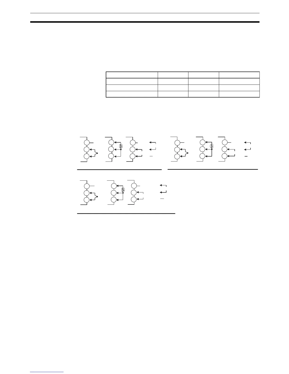
Input • Make the connections as shown below, using terminals 3 to 5 for the
E5CN, pins 1 to 3 for the E5CN-U, and pins 18 to 20 for the E5AN/EN,
and matching the input types.
Control Output 1 • Outputs are sent from terminals 1 and 2 with the E5CN, from pins 4 to 6
with the E5CN-U, and from pins 3 and 4 with the E5AN/EN. The following
diagrams show the available outputs and their internal equalizing circuits.
Input power supply E5CN E5CN-U E5AN/EN
100 to 240 VAC, 50/60 Hz 7.5 VA 6 VA 10 VA
24 VAC, 50/60 Hz 5 VA 3 VA 5.5 VA
24 VDC (no polarity) 3 W 2 W 4 W
E5CN E5CN-U
E5AN/EN
+
−
−
+
+
V
+
−
−
+
+
−
v
+
−
−
+
−
V
+
Analog input
Platinum resistance
thermometer
Thermocouple
Analog input
Platinum resistance
thermometer
Thermocouple
Analog input
Platinum resistance
thermometer
Thermocouple
mA
mA
mA
Do not
use.
Do not
use.
Do not
use.
Do not
use.
Do not
use.
3
4
5
3
4
5
3
4
5
3
2
1
3
2
1
3
2
1
Do not
use.
Do not
use.
Do not
use.
Do not
use.
18
19
20
18
19
20
18
19
20