130
Displaying PV/SV Status Section 4-21
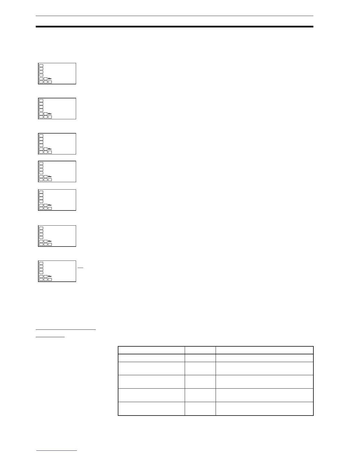
Operating Procedure This procedure sets the Control Output 1 ON/OFF Alarm Setting parameter to
10 (1,000 times).
4-21 Displaying PV/SV Status
4-21-1 PV and SV Status Display Functions
PV Status Display
Function
The PV in the PV/SP, PV, or PV/Manual MV Display and the control and alarm
status specified for the PV status display function are alternately displayed in
0.5-s cycles.
Initial Setting Level
1. Press the O Key for at least three seconds to move from the operation
level to the initial setting level.
Initial Setting Level
2. Select the Move to Advanced Function Setting Level parameter by press-
ing the M Key.
Advanced Function Setting Level
3. Use the D Key to enter the password (“−169”). It is possible to move to
the advanced function setting level by either pressing the M Key or wait-
ing two seconds without pressing any key.
4. Press the M Key to select the Control Output 1 ON/OFF Count Alarm Set
Value parameter.
5. Use the U Key to set the parameter to 10.
Initial Setting Level
6. Press the O Key for at least one second to move to the initial setting lev-
el.
Operation Level
7. Press the O Key for at least one second to move to the operation level.
in-t
5
Input Type
amov
-169
Move to Ad-
vanced Function
Setting Level
init
off
Parameter
Initialization
ra1
0
Control Output
1 ON/OFF
Count Alarm
Set Value
ra1
10
Control Output
1 ON/OFF
Count Alarm
Set Value
in-t
5
Input Type
C
25
100
al
▲
▲
Set value Symbol Function
OFF off No PV status display
Manual manu MANU is alternately displayed during
manual control.
Stop stop STOP is alternately displayed while oper-
ation is stopped.
Alarm 1 alm1 ALM1 is alternately displayed during
Alarm 1 status.
Alarm 2 alm2 ALM2 is alternately displayed during
Alarm 2 status.