63
Using Heater Burnout, Heater Short, and Heater Overcurrent Alarms Section 3-10
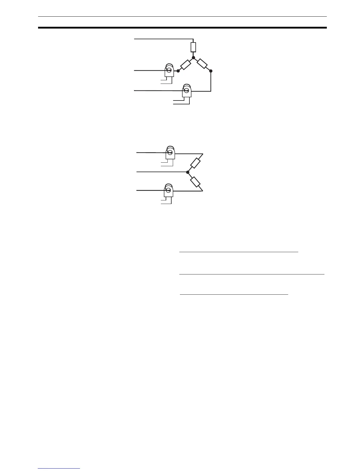
3. V connecting lines: Refer to the following diagram for CT installation posi-
tions.
Note Heater voltage fluctuations are not considered here, so be take that
into account when setting the detection current.
3-10-3 Calculating Detection Current Values
• Calculate the set value using the following equation:
• To set the current for heater burnout when two or more heaters are con-
nected through the CT, use the value from when the heater with the small-
est current burns out. If all of the heaters have the same current, use the
value from when any one of them burns out.
• Make sure that the following conditions are satisfied:
Heater with a current of less than 10.0 A:
(Current value at normal operation)
− (Current value at heater burnout) ≥
1A
When the difference is less than 1 A, detection is unstable.
Heater with a current of 10.0 A or more:
(Current value at normal operation)
− (Current value at heater burnout) ≥
2.5 A
When the difference is less than 2.5 A, detection is unstable.
CT
CT
Load
Load
Load
Load (such as a heater)
AC line
Product
To CT input
Product
To CT input
CT
CT
Load
Load
Load (such as a heater)
AC line
Product
To CT input
Product
To CT in
ut
Heater Burnout Detection 1/2 set value =
Normal current value + Burnout current value
2
HS Alarm 1/2 set value =
Leakage current value (output OFF) + HS current value
2
Heater overcurrent 1/2 set value =
Normal current value + Overcurrent value
2