246
Calibrating Analog Input (Analog Input)
Section 6-6
6-6 Calibrating Analog Input (Analog Input)
6-6-1 Calibrating a Current Input
In this example, calibration is shown for a Controller with an Analog Input, with
a current input set as the input type.
5. When the M Key is pressed, the status changes as shown to the left.
The No. 2 display at this time shows the currently entered count value in
hexadecimal. Set the STV to 54 mV.
Allow the count value on the No. 2 display to fully stabilize, then press the
D Key to temporarily register the calibration settings.
If this count value is outside of the specified range, the No. 2 display will
flash and the count value will not be temporarily registered.
6. When the M Key is pressed, the status changes as shown to the left.
Set the STV to
−6 mV.
Allow the count value on the No. 2 display to fully stabilize, then press the
D Key to temporarily register the calibration settings.
If this count value is outside of the specified range, the No. 2 display will
flash and the count value will not be temporarily registered.
7. When the M Key is pressed, the status changes as shown to the left.
The data to be temporarily registered is not displayed if it is not complete.
Press the U Key. The No. 2 display changes to yes. Release the key and
wait two seconds or press the M Key. This stores the temporarily regis-
tered calibration data to EEPROM.
To cancel the saving of temporarily registered calibration data to EE-
PROM, press the M Key (while no is displayed in the No. 2 display) with-
out pressing the U Key.
8. The calibration mode is ended by turning the power OFF.
t-54
b9a5
t--6
2988
str
no
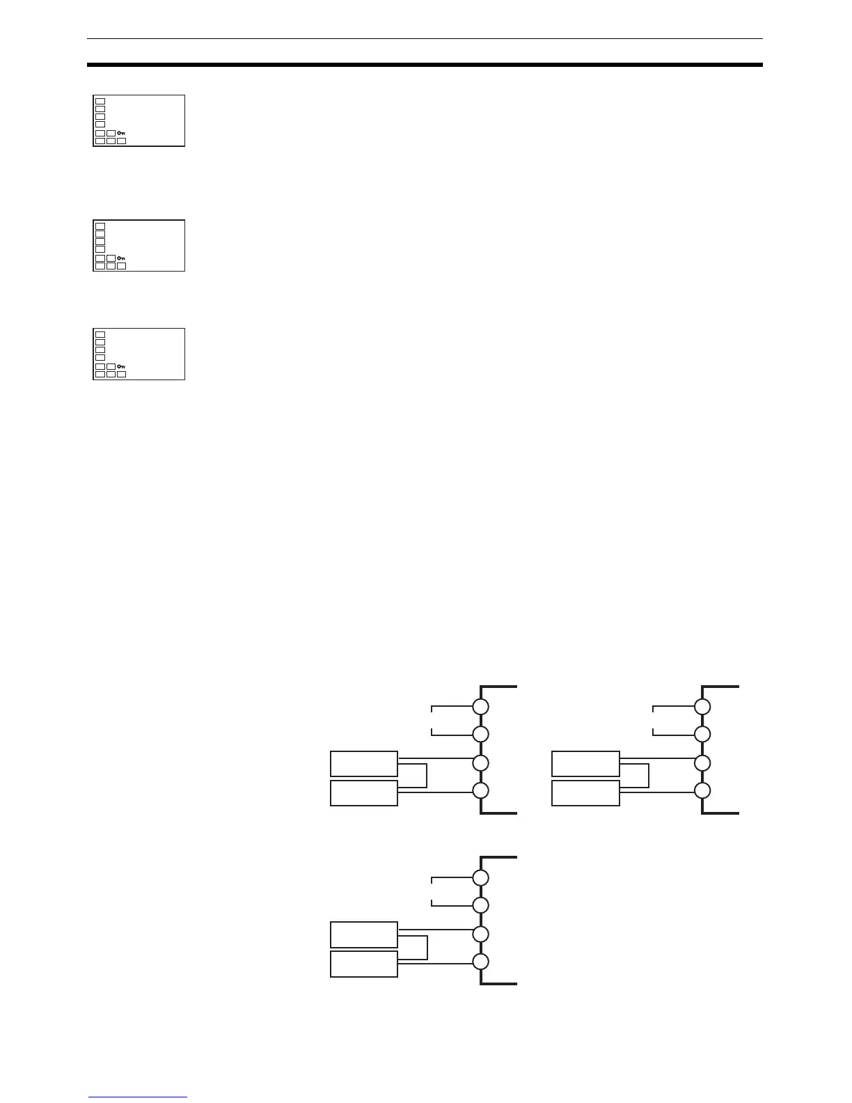
1,2,3... 1. Connect the power supply.
2. Connect an STV and DMM to the current input terminals, as shown in the
following diagram.
3. Turn the power ON.
STV
E5CN
DMM
−
+
9
10
4
5
Input power supply
STV
E5AN/EN
DMM
−
+
1
2
19
20
Input power supply
STV
E5CN-U
DMM
−
+
10
11
2
1
Input power supply