245
Analog Input Calibration (Thermocouple/Resistance Thermometer Input)
Section 6-5
6-5 Analog Input Calibration (Thermocouple/Resistance
Thermometer Input)
In this example, calibration is shown for a Controller with a Thermocouple/
Resistance Thermometer Universal Input, with an analog input (0 to 50 mV)
set as the input type.
Input types 1, 2, 3, 4: Allow the count value on the No. 2 display to fully stabilize, then press the D Key
to temporarily register the calibration settings.
If this count value is outside of the specified range, the No. 2 display will flash
and the count value will not be temporarily registered.
6. When the M Key is pressed, the status changes as shown to the left.
Set the 6-dial to 10
Ω.
Allow the count value on the No. 2 display to fully stabilize, then press the
D Key to temporarily register the calibration settings.
If this count value is outside of the specified range, the No. 2 display will
flash and the count value will not be temporarily registered.
7. When the M Key is pressed, the status changes as shown to the left.
The data to be temporarily registered is not displayed if it is not complete.
Press the U Key. The No. 2 display changes to yes. Release the key and
wait two seconds or press the M Key. This stores the temporarily regis-
tered calibration data to EEPROM.
To cancel the saving of temporarily registered calibration data to EE-
PROM, press the M Key (while no is displayed in the No. 2 display) with-
out pressing the U Key.
8. The calibration mode is quit by turning the power OFF.
p140
e26b
p-10
4543
str
no
STV
E5CN
DMM
−
+
9
10
STV
E5CN-U
DMM
−
+
10
11
2
1
4
5
Input power supply Input power supply
STV
E5AN/EN
DMM
−
+
1
2
19
20
Input power supply
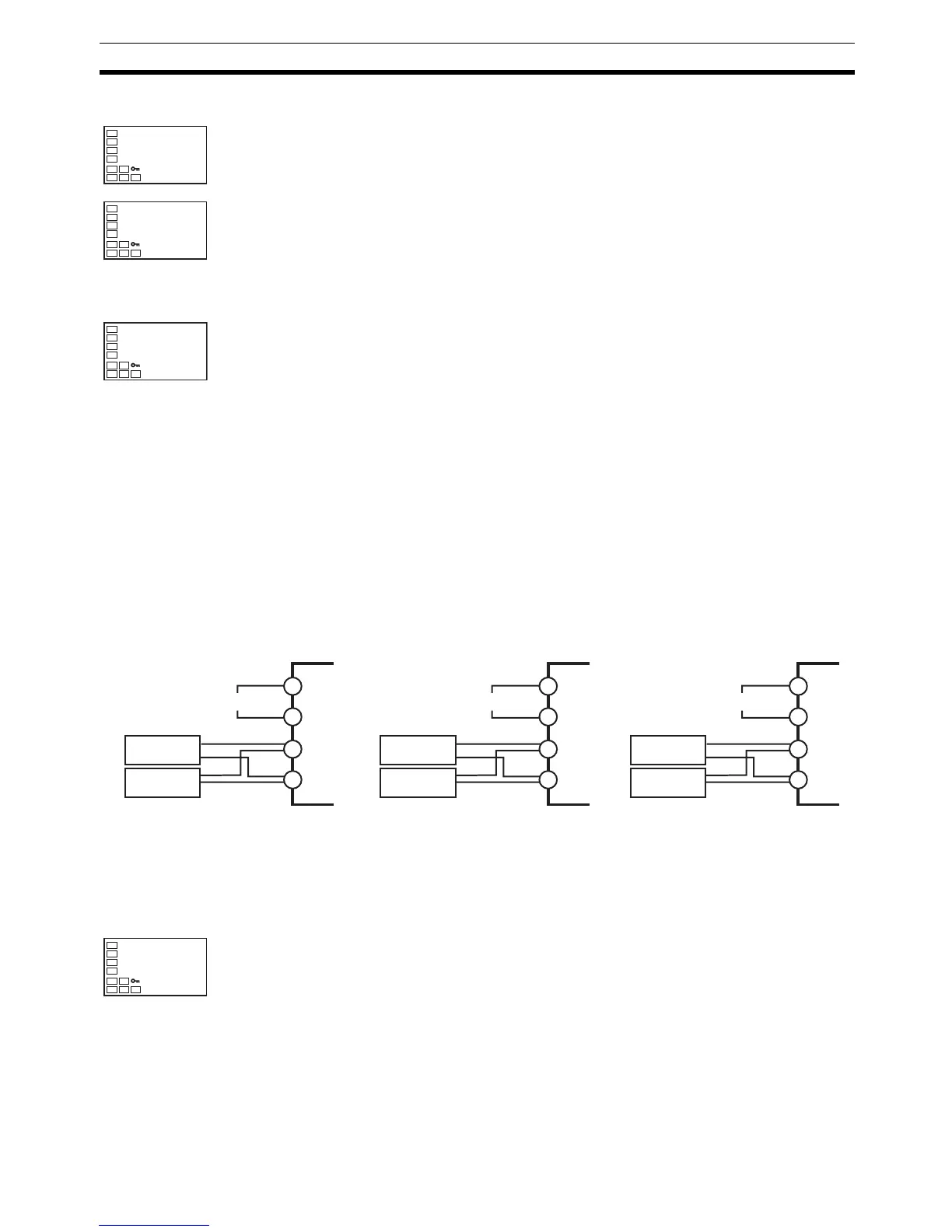
1,2,3... 1. Connect the power supply.
2. Connect an STV and DMM to the analog input terminals (same as ther-
mocouple inputs), as shown in the figure above.
3. Turn the power ON.
4. Move to the calibration level.
This starts the 30-minute aging timer. This timer provides an approximate
timer for aging. After 30 minutes have elapsed, the No. 2 display changes
to 0. You can advance to the next step in this procedure even if 0 is not
displayed.
adj
30