50
Determining PID Constants (AT, ST, Manual Setup) Section 3-8
Setting the Hysteresis
Operating Procedure Set the hysteresis to 2.0°C.
3-8 Determining PID Constants (AT, ST, Manual Setup)
3-8-1 AT (Auto-tuning)
• When AT is executed, the optimum PID constants for the set point at that
time are set automatically. A method (called the limit cycle method) for
forcibly changing the manipulated variable and finding the characteristics
of the control object is employed.
• Either 40% AT or 100% AT can be selected depending on the width of MV
variation in the limit cycle. In the AT Execute/Cancel parameter, specify
at-2 (100% AT) or at-1 (40% AT). To cancel AT, specify off (AT can-
cel).
• Only 100% AT can be executed for heating and cooling control.
• AT cannot be executed when control has stopped or during ON/OFF con-
trol.
• The results of AT are reflected in the Proportional Band (P), Integral Time
(I), and Derivative Time (D) parameters in the adjustment level.
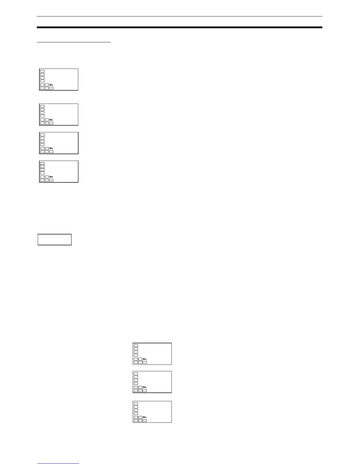
Operation Level
1. Press the O Key to move from the operation level to the adjustment level.
Adjustment Level
2. The Adjustment Level Display parameter will be displayed in the adjust-
ment level.
3. Select the Hysteresis (Heating) parameter by pressing the M Key.
4. Press the U and D Keys to set the hysteresis (2.0 in this example). Ei-
ther press the M Key or wait for at least two seconds after setting the hys-
teresis value to confirm the setting.
5. To return to the operation level, press the O Key.
C
25
200
P