137
Logic Operations Section 4-22
(2) Turns ON when either the control output 1 or 2 ON/OFF count alarm is
ON.
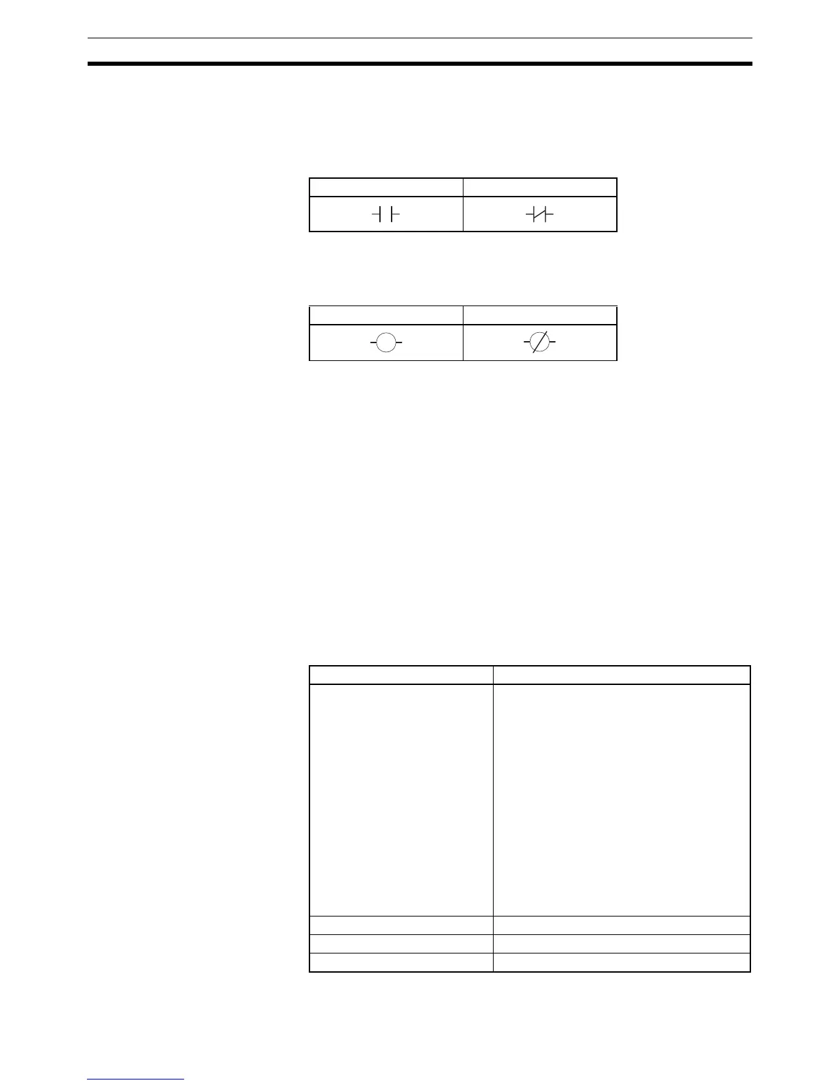
5. Switching between Normally Open and Normally Closed for Inputs A to D
Click the condition to switch between normally open and normally closed
inputs A to D.
6. Switching between Normally Open and Normally Closed for Work Bits
Click the condition to switch between normally open and normally closed
work bits.
7. Setting ON Delay Times
When an input with ON delay turns ON, the output will turn ON after the
set delay time has elapsed. The setting range is 0 to 9,999. The default is
0 (disabled).
8. Setting OFF Delay Times
When an input with OFF delay turns OFF, the output will turn OFF after the
set delay time has elapsed. The setting range is 0 to 9,999. The default is
0 (disabled).
9. Switching ON/OFF Delay Time Unit
Select either seconds or minutes for the ON/OFF delay time unit. The de-
fault is seconds.
10. Selecting the Number of Multi-SP Uses
Select the number of Multi-SP uses from 0 to 2.
11. Changing Event Input Data
Select the event input conditions from the following setting ranges.
Normally open Normally closed
Normally open Normally closed
Parameter name Setting range
Event Input Data 1 0: Not assigned.
1: Event input 1 (external input)
2: Event input 2 (external input)
3: Event input 3 (external input)
4: Event input 4 (external input)
5: Work bit 1
6: Work bit 2
7: Work bit 3
8: Work bit 4
9: Work bit 5
10: Work bit 6
11: Work bit 7
12: Work bit 8
Event Input Data 2 Same as for event input data 1
Event Input Data 3 Same as for event input data 1
Event Input Data 4 Same as for event input data 1