229
Advanced Function Setting Level Section 5-8
(2) Alarms 1 to 3, heater burnout, HS alarms, and heater overcurrent latches
are cancelled.
(3) For details on auto/manual operations using the PF Key, refer to 4-13 Per-
forming Manual Control.
■ Related Parameters
Monitor/setting item 1 to 5 (advanced function setting level): Page 229
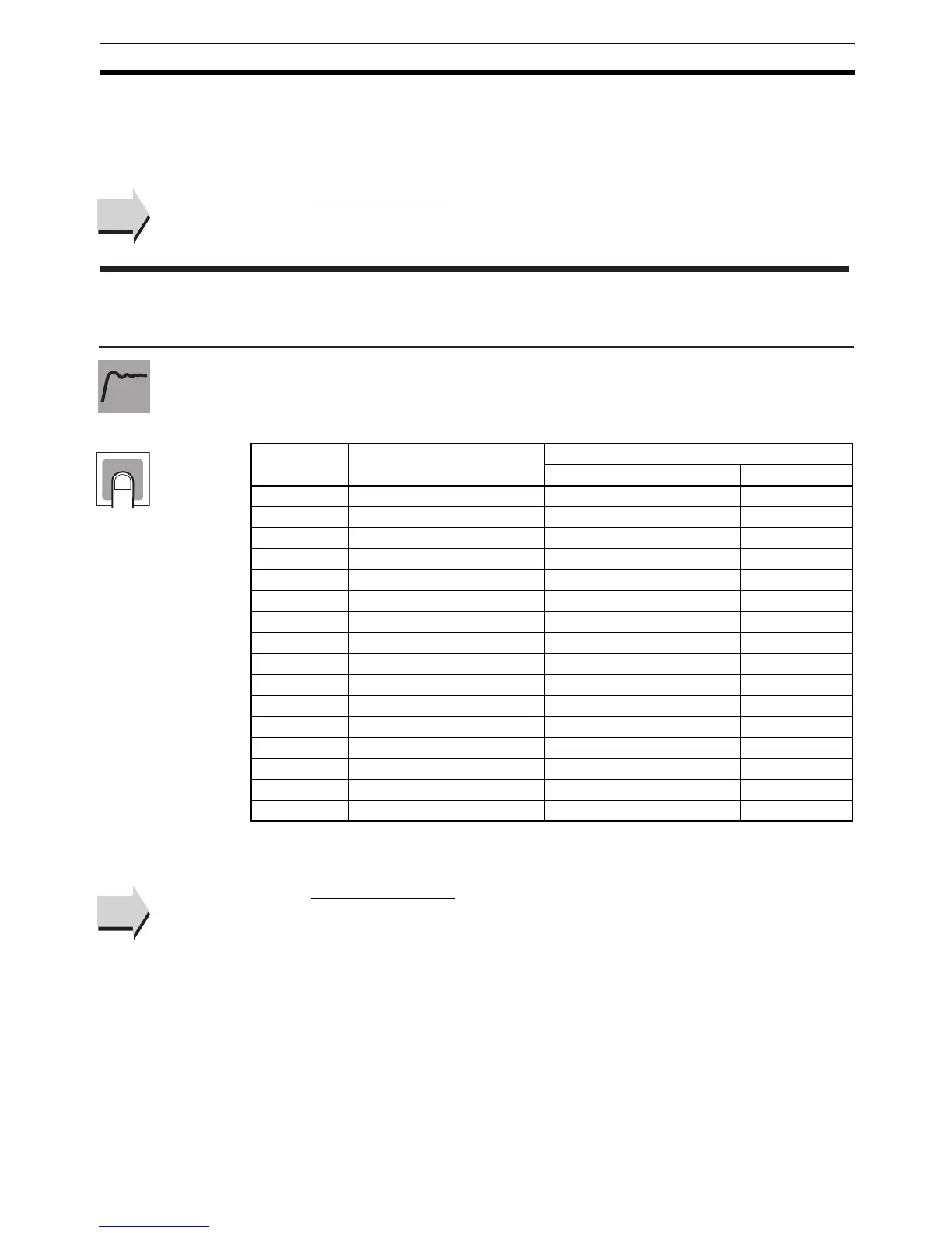
• Set the PF Key parameter to Monitor/Setting Item to enable using the
function key to display monitor/setting items. The items that will be dis-
played are set using the Monitor/Setting Item 1 to 5 parameters. The set-
tings are listed in the following table.
Note The MV for heating and cooling control is set in the MV Display Selection
parameter.
■ Related Parameters
PF setting: Page 228, MV display selection: Page 230 (advanced function set-
ting level)
See
See
pfd* Monitor/Setting Item * (*: 1 to 5)
The PF Setting parameter must be
set to PFDP.
Function
Setting
Set value Setting Remarks
Monitor/Setting Symbol
0 Disabled ---
1 PV/SP/Multi-SP Can be set. (SP) ---
2 PV/SP/MV (See note.) Can be set. (SP) ---
3 PV/SP/Soak time remain Can be set. (SP) ---
4 Proportional band (P) Can be set. p
5 Integral time (I) Can be set. i
6 Derivative time (D) Can be set. d
7 Alarm value 1 Can be set. al-1
8 Alarm value upper limit 1 Can be set. al1h
9 Alarm value lower limit 1 Can be set. al1l
10 Alarm value 2 Can be set. al-2
11 Alarm value upper limit 2 Can be set. al2h
12 Alarm value lower limit 2 Can be set. al2l
13 Alarm value 3 Can be set. al-3
14 Alarm value upper limit 3 Can be set. al3h
15 Alarm value lower limit 3 Can be set. al3l
See
See