242
Thermocouple Calibration (Thermocouple/Resistance Thermometer Input)
Section 6-3
In this example, calibration is shown for a Controller with a Thermocouple/
Resistance Thermometer Universal Input, with thermocouple/infrared temper-
ature sensor set as the input type.
1,2,3... 1. Connect the power supply.
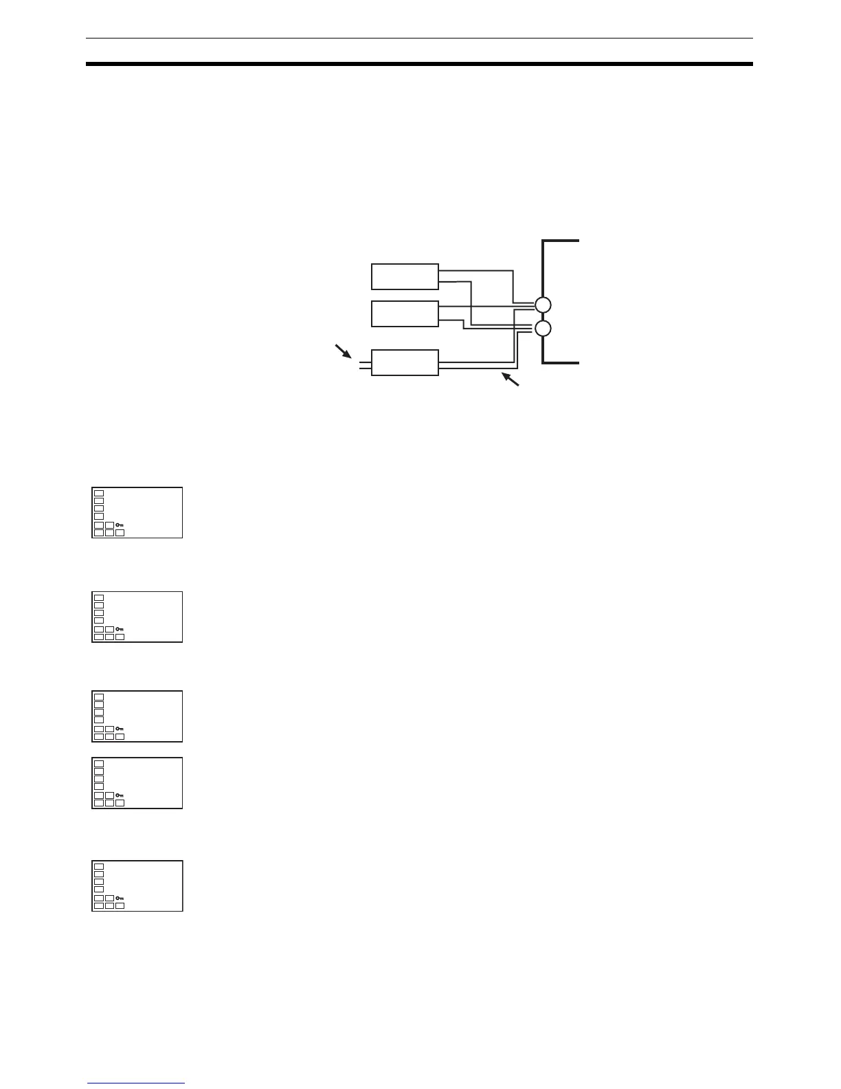
2. Connect a standard DC current/voltage source (STV), precision digital
multimeter (DMM), and contact junction compensator (e.g., a zero con-
troller as in the figure) to the thermocouple input terminals, as shown in
the figure below.
3. Turn the power ON.
4. Move to the calibration level.
This starts the 30-minute aging timer. This timer provides an approximate
timer for aging. After 30 minutes have elapsed, the No. 2 display changes
to 0. You can advance to the next step in this procedure even if 0 is not
displayed.
Input types 5, 7, 11, 12, 15:
Input types 6, 8, 9, 10, 13, 14, 16,
17, 18, 19, 20, 21, 22, 24, 25:
5. When the M Key is pressed, the status changes as shown to the left.
The No. 2 display at this time shows the currently entered count value in
hexadecimal. Set the STV as follows:
• Input types 5, 7, 11, 12, 15: Set to 54 mV.
• Input types 6, 8, 9, 10, 13, 14, 16, 17, 18, 19, 20, 21, 22, 24, 25:
Set to 24 mV.
Allow the count value on the No. 2 display to fully stabilize, then press the
D Key to temporarily register the calibration settings.
If this count value is outside of the specified range, the No. 2 display will
flash and the count value will not be temporarily registered.
6. When the M Key is pressed, the status changes as shown to the left.
Set the STV to
−6 mV.
Allow the count value on the No. 2 display to fully stabilize, then press the
D Key to temporarily register the calibration settings.
If this count value is outside of the specified range, the No. 2 display will
flash and the count value will not be temporarily registered.
7. Press the M Key. The display changes as shown on the left. Set the STV
to 700 mV.
Allow the count value on the No. 2 display to fully stabilize, then press the
D Key to temporarily register the calibration settings.
If this count value is outside of the specified range, the No. 2 display will
flash and the count value will not be temporarily registered.
STV
DMM
OUTPUT INPUT
−
+
Leave open.
Compensating conductor of currently selected
thermocouple.
Use K thermocouple compensating conductor
for E, R, S, B, W, and PLII thermocouples and
for an infrared temperature sensor.
Zero
controller
adj
30
t-54
b9a5
t-24
e220
t--6
2988
c700-
ba13