255
Appendix
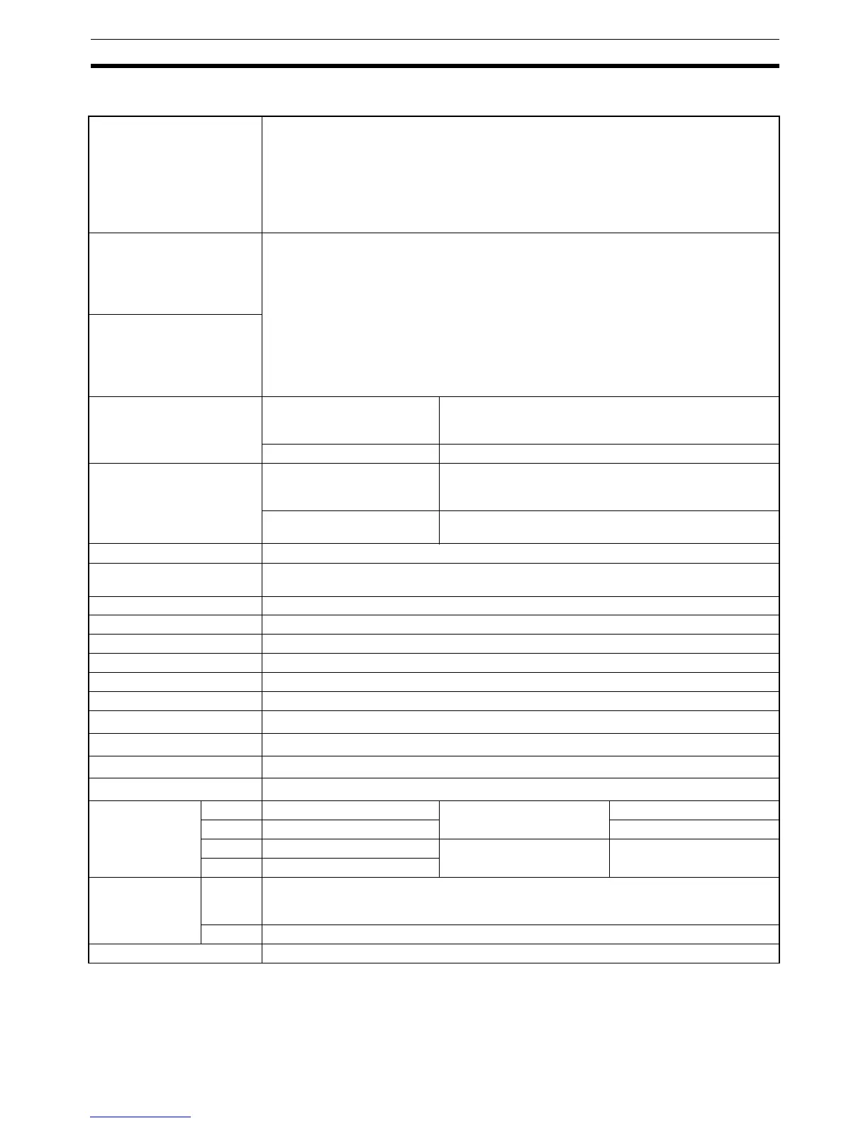
Characteristics
Note (1) The indication accuracy of K thermocouples in the −200 to 1,300°C range, T and N thermocouples
at a temperature of
−100°C or less, and U and L thermocouples at any temperature is ±2°C ±1 digit
maximum. The indication accuracy of B thermocouples at a temperature of 400
°C to 800±3°C or
less is not specified. The indication accuracy of R and S thermocouples at a temperature of 200
°C
Indication accuracy
(ambient temperature of
23°C)
Thermocouple (See note 1.):
E5CN/AN/EN: (±0.3% of indication value or ±1°C, whichever is greater) ±1 digit max.
E5CN-U: (±1% of indication value or ±2°C, whichever is greater) ±1 digit max.
Platinum resistance thermometer:
(±0.2% of indication value or ±0.8°C, whichever is greater) ±1 digit max.
Analog input: ±0.2% FS ±1 digit max.
CT input: ±5% FS ±1 digit max.
Temperature variation
influence (See note 2.)
Thermocouple (R, S, B, W, PLII)
(±1% of PV or ±10°C, whichever is greater) ±1 digit max. (E5CN)
(±2% of PV or ±10°C, whichever is greater) ±1 digit max. (E5CN-U)
Other thermocouples:
(±1% of PV or ±4°C, whichever is greater) ±1 digit max. (E5CN)
(±2% of PV or ±4°C, whichever is greater) ±1 digit max. (E5CN-U)
*K thermocouple at −100°C max: ±10°C max.
Platinum resistance thermometer:
(±1% of PV or ±2°C, whichever is greater) ±1 digit max.
Analog input: ±1% FS ±1 digit max.
Voltage variation influence
(See note 2.)
Hysteresis Controllers with Thermocou-
ple/Resistance Thermometer
Universal Inputs
0.1 to 999.9°C or °F)
(in units of 0.1°C or °F) (See note 3.)
Controllers with Analog Inputs 0.01% to 99.99% FS (in units of 0.01% FS)
Proportional band (P) Controllers with Thermocou-
ple/Resistance Thermometer
Universal Inputs
0.1 to 999.9°C or °F)
(in units of 0.1 EU) (See note 3.)
Controllers with Analog Inputs 0.1% to 999.9% FS (in units of 0.1% FS)
0.01% to 99.99% FS (in units of 0.01% FS)
Integral time (I) 0 to 3,999 s (in units of 1 s)
Derivative time (D) 0 to 3,999 s (in units of 1 s)
When RT is ON: 0.0 to 999.9 (in units of 0.1 s)
Control Period 0.5, 1 to 99 s (in units of 1 s)
Manual reset value 0.0% to 100.0% (in units of 0.1%)
Alarm setting range −1,999 to 9,999 (decimal point position depends on input type)
Sampling period 250 ms
Insulation resistance 20 MΩ min. (at 500 VDC)
Dielectric strength 2,300 VAC, 50/60 Hz for 1 min between terminals of different charge
Malfunction vibration
10 to 55 Hz, 20 m/s
2
for 10 min each in X, Y and Z directions
Vibration resistance
10 to 55 Hz, 20 m/s
2
for 2 hr each in X, Y, and Z directions
Malfunction shock
100 m/s
2
, 3 times each in X, Y, and Z directions
Shock resistance
300 m/s
2
, 3 times each in X, Y, and Z directions
Weight E5CN Approx. 150 g Adapter: approx. 10 g Terminal cover: approx. 10 g
E5CN-U Approx. 110 g ---
E5AN Approx. 310 g Adapter: approx. 100 g Terminal cover: approx.
1.6 g per cover
E5EN Approx. 260 g
Degree of protec-
tion
E5CN
E5AN
E5EN
Front panel: IP66
Rear case: IP20
Terminals: IP00
E5CN-U Front panel: IP50, rear case: IP20, terminals: IP00
Memory protection EEPROM (non-volatile memory) (number of writes: 1,000,000)