10
I/O Configuration and Main Functions Section 1-2
• Inputs with the following specifications can be connected for analog input
(i.e., E5_N-@@@@L):
Current input: 4 to 20 mA DC, 0 to 20 mA DC
Voltage input: 1 to 5 VDC, 0 to 5 V DC, 0 to 10 V DC
Control Outputs • A control output can be a relay, voltage (for driving SSR), or current out-
put, depending on the model.
• Long-life relay outputs use semiconductors for switching when closing
and opening the circuit, thereby reducing chattering and arcing and
improving durability. However, if high levels of noise or surge are imposed
between the output terminals, short-circuit faults may occasionally occur.
If the output becomes permanently shorted, there is the danger of fire due
to overheating of the heater. Design safety into the system, including
measures to prevent excessive temperature rise and spreading of fire.
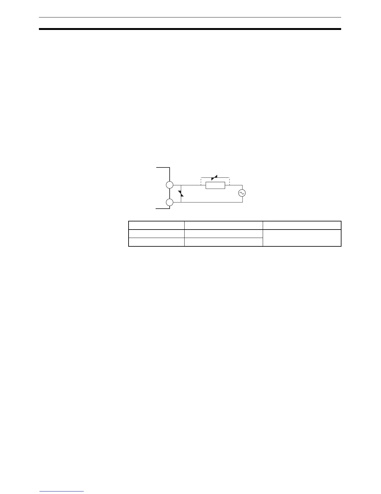
Take countermeasures such as installing a surge absorber. As an addi-
tional safety measure, provide error detection in the control loop. (Use the
Loop Burnout Alarm (LBA) and HS alarm that are provided for the E5@N.)
Select a surge absorber that satisfies the following conditions.
• Always connect an AC load to a long-life relay output. The output will not
turn OFF if a DC load is connected.
Alarms • Set the alarm type and alarm value or the alarm value upper and lower
limits.
• If necessary, a more comprehensive alarm function can be achieved by
setting a standby sequence, alarm hysteresis, auxiliary output close in
alarm/open in alarm, alarm latch, alarm ON delay, and alarm OFF delay.
• If the Input Error Output parameter is set to ON, the output assigned to
alarm 1 function will turn ON when an input error occurs.
Control Adjustment • Optimum PID constants can be set easily by performing AT (auto-tuning)
or ST (self-tuning).
Event Inputs • With the E53-CN@B@N2 for the E5CN or the E5AN/EN-@M@-500-N with
the E53-AKB for the E5AN/EN, the following functions can be executed
using event inputs: switching set points (multi-SP, 4 points max.), switch-
ing RUN/STOP, switching between automatic and manual operation, start-
ing/resetting the program, inverting direct/reverse operation, 100% AT
execute/cancel, 40% AT execute/cancel, setting change enable/disable,
and canceling the alarm latch.
Heater Burnout, HS Alarm,
and Heater Overcurrent
• With the E53-CN@H@N2 or E53-CN@HH@N2 for the E5CN, or the
E5AN/EN-@@H@-500-N or E5AN/EN-@@HH@-500-N, the heater burnout
detection function, HS alarm function, and heater overcurrent detection
function can be used.
Communications
Functions
• Communications functions utilizing CompoWay/F (See note 1.), SYSWAY
(See note 2.), or Modbus (See note 3.) can be used.
Voltage used Varistor voltage Surge resistance
100 to 120 VAC 240 to 270 V 1,000 A min.
200 to 240 VAC 440 to 470 V
1
2
Long-life
relay output
Varistor
Varistor
Inductive
load