34
Wiring Terminals Section 2-2
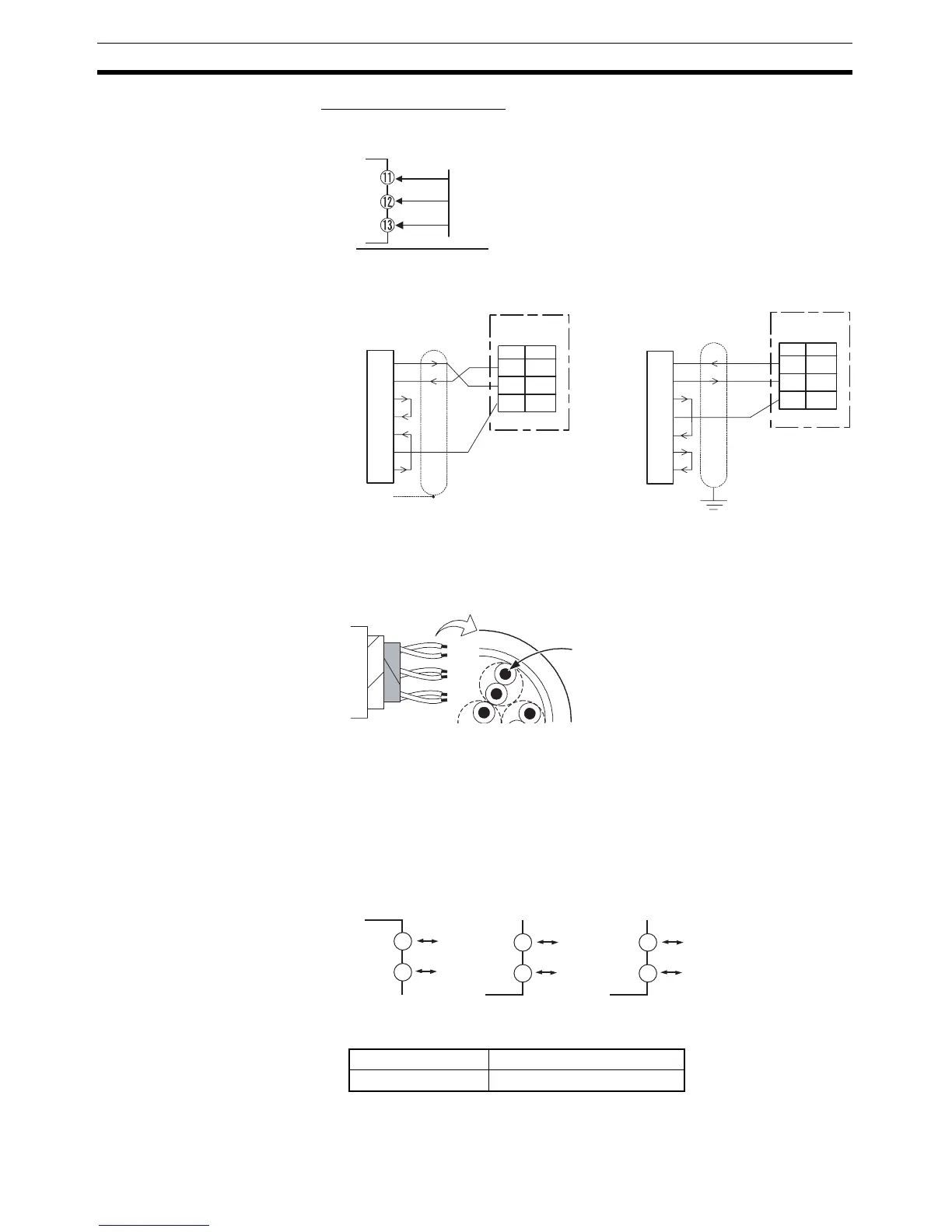
RS-232C (E5AN/EN Only)
• When communications are to be used with the E53-EN01, connect com-
munications cable across terminals 11 to 13.
• A 1:1 connection is used. The maximum cable length is 15 m. To extend
the transmission path, use the OMRON Z3R RS-232C Optical Interface.
• Use AWG24 (cross-sectional area: 0.205 mm
2
) to AWG14 (cross-sec-
tional area: 2.081 mm
2
) shielded twisted-pair cable.
External Power Supply for
ES1B
• Connect terminals 11 and 12 when using the E53-CN@@PH@N2 as the
external power supply for the ES1B.
• Connect terminals 14 and 15 when using the E53-CN@@PBN2 as the
external power supply for the ES1B.
• Connect terminals 14 and 15 when using the E5AN/EN-@@P@-N as the
external power supply for the ES1B.
• The following table provides the specifications of the external power sup-
ply for ES1B.
Note Contact your OMRON representative for information on using the
external power supply for ES1B for other applications.
SD
RD
SG
RS-232C
RD (RXD)
SD (TXD)
ER (DTR)
SG
DR (DSR)
RS (RTS)
CS (CTS)
3
4
5
6
7
2
8
11
No.
12
13
SD
RD
SG
1
FG
SD (TXD)
RD (RXD)
RS (RTS)
CS (CTS)
DR (DSR)
SG
ER (DTR)
3
4
5
6
7
20
2
11
No.
12
13
SD
RD
SG
E53-EN01 (for E5AN/EN)
Host computer
RS-232C: 25-pin
E5AN/EN
RS-232C
Host computer (DOS/V)
RS-232C: 9-pin
E5AN/EN
RS-232C
Cross-sectional area of
conductor
AWG24: 0.205 mm
2
AWG14: 2.081 mm
2
Output voltage 12 VDC ±10%
Output current 20 mA max.
11
E53-CN@@PH@N2 E53-CN@@PBN2
12
(−)
(+)
14
15
(−)
(+)
E5AN/EN-@@P@-N
14
15
(−)
(+)