3-8 Installing the Controller Link Interface Unit
3-48
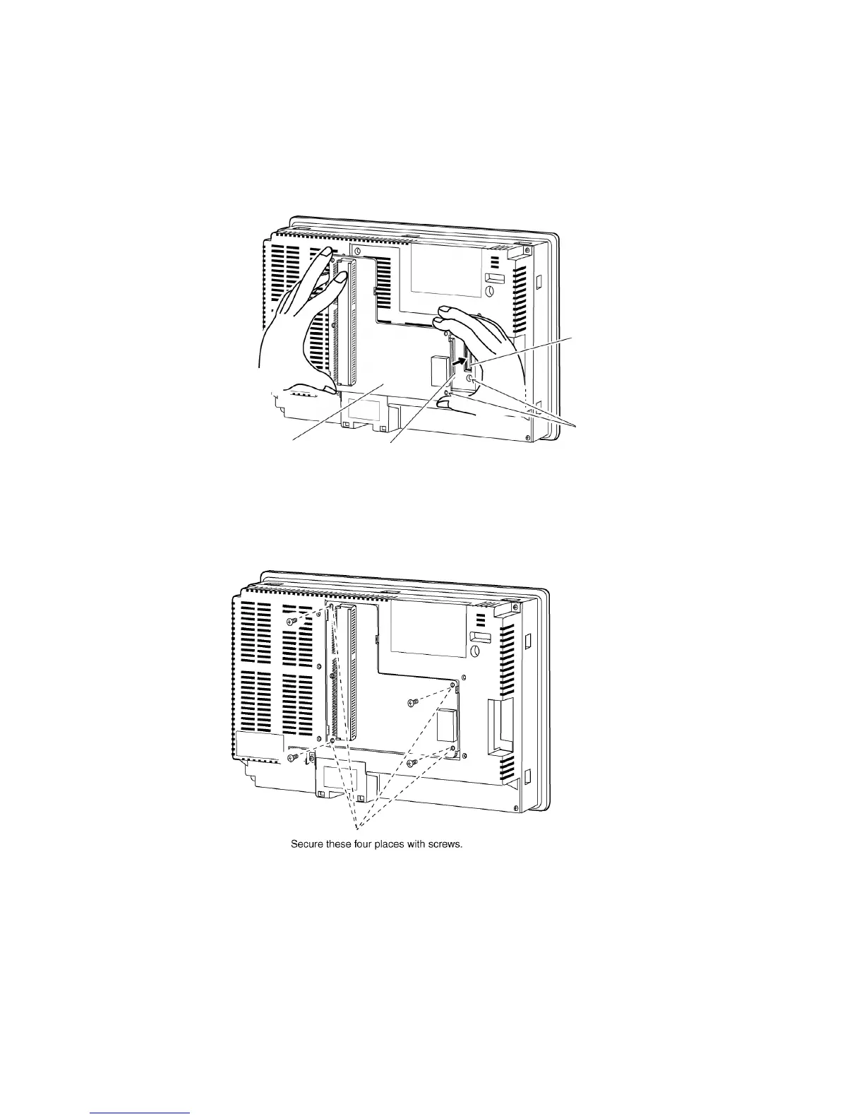
z Connecting and Disconnecting
1. Mount the Connector Conversion Board onto the back of the PT so that its expansion in-
terface connector is inserted into the expansion interface connector on the back of the
PT and the respective screw holes are aligned. Hold the Board by the corners keeping it
parallel to back of the PT.
PT’s expansion
interface connector
Connector Conversion
Board
Connector Conversion Board’s
expansion interface connector
Hold the four corners and insert straight
to the expansion interface connector on
the PT.
Align the positions of the holes
2. Secure the four corners of the Connector Conversion Board with screws.