Appendix 7 Preparing Connecting Cables for Bar Code Readers
A-43
Appendix 7 Preparing Connecting Cables for Bar
Code Readers
Refer to the following information when preparing the connecting cables for connecting
the V520-RH21-6 Bar Code Reader.
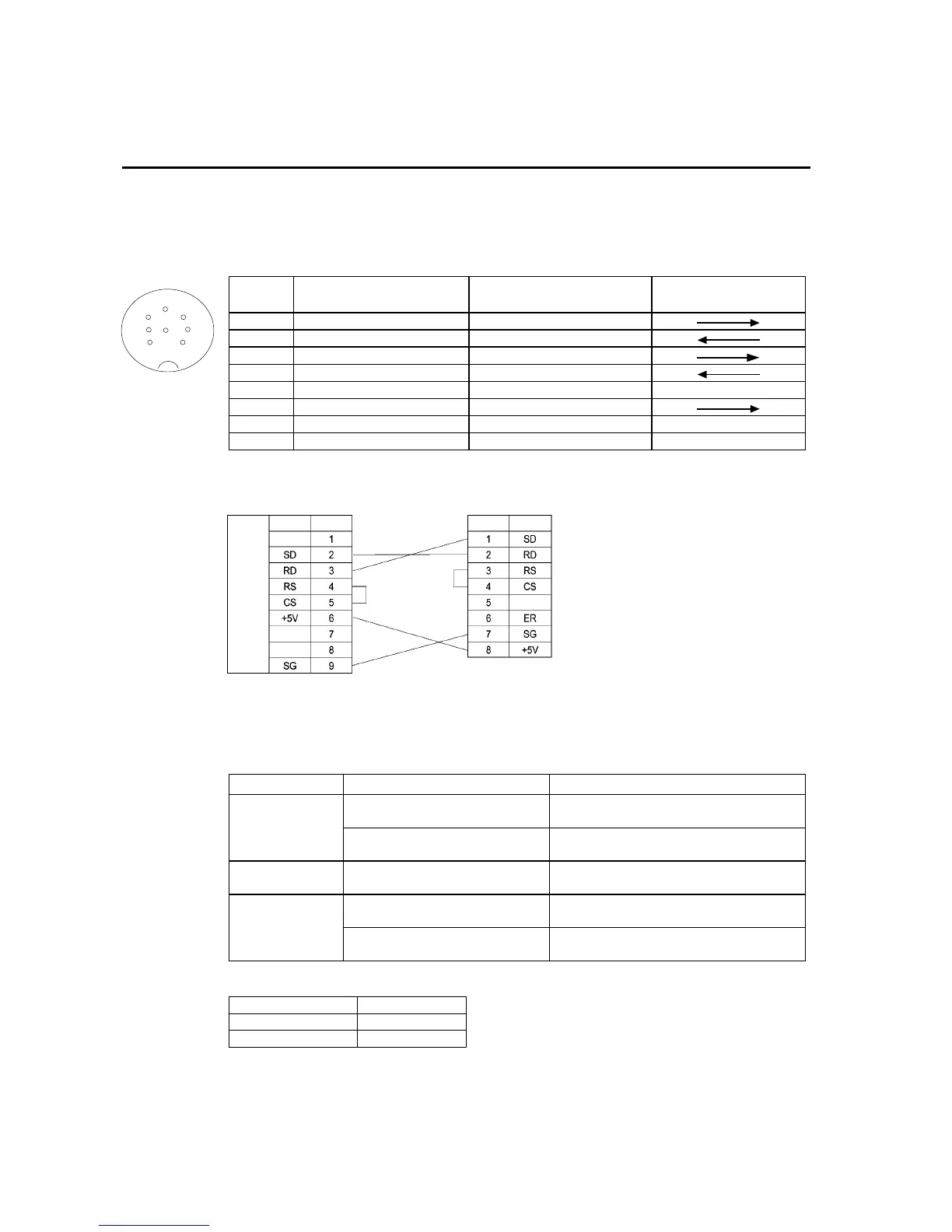
• Connector Pin Arrangement
Pin
number
Signal name Abbreviation
Signal direction
V520-RH21-6 PT
1 Send data SD (TXD)
2 Receive data RD (RXD)
3 Request to send RS (RTS)
4 Clear to send CS (CTS)
5 Not connected.
6 Data terminal ready ER (DTR)
7 0 V SG
8 Power supply (Vcc) +5 V
• Wiring Method
PT
V520-RH21-6
RS-232C
interface
Signal Pin No. Signal Pin No.
When connecting to the 5-V output of the PT’s serial port, use a cable length of less than
2 m. If the cable is 2 m or longer, connect pins 7 and 8 of the Bar Code Reader to an ex-
ternal power supply.
• Connector Types
Use the following products to assemble the connecting cable.
Name Model Details
XM2A-0901 9-pin type
Manufactured by OMRON (PT side)
Connector
TCS2280-01-2011 8-pin DIN type Hoshiden, Co., Ltd.
Panel-mounting type
Connector hood XM2S-0911 9-pin type
Manufactured by OMRON.
AWG28 × 5P IFVV-SB
Multiconductor shielded cable
Manufactured by Fujikura Densen.
Cable
CO-MA-VV-SB 5P × 28AWG
Multiconductor shielded cable
Manufactured by Hitachi Densen.
Use the following cables if the V400-H111 or V400-H211 is used.
Model Cable length
V400-W20-2M 2 m
V400-W20-5M 5 m
1
2
3
4
5
7
8
6
Connector pin
arrangement at
computer