3-8 Installing the Controller Link Interface Unit
3-54
3-8-4 Wiring
This section describes the method for wiring the network communications cable to the Con-
troller Link Support Board.
z Wiring the Communications Cable
Wire the communications cable to connect identical signals.
Precautions
for Safe Use
• Use the cable specified for the communications cable.
• Keep communications cables separated from power lines or high-tension
lines to prevent influences from electronic noise.
• Ground the shield of the communications cable at one end of the network.
Do not ground the shield at both ends.
• Do not connect the shield cable of the communications cable to a ground
that is also being used for power-system devices, such as inverters.
• Do not run wiring outdoors. If outdoor wiring is necessary, take protective
measures against lightening, such as underground wiring or wiring inside
pipes.
• Always turn OFF the power to PT before connecting the communications
cable or installing/removing the connector.
• Use the connector attached to the Controller Link Support Board.
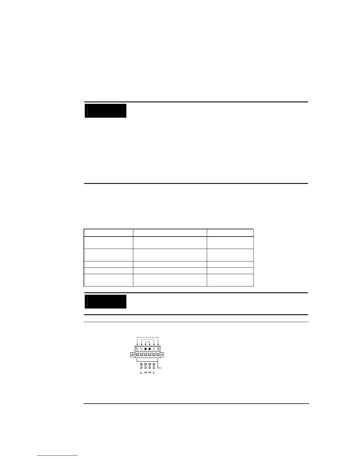
Connecting the Communications Cable
Connect the communications cable to the Controller Link Support Board after first connect-
ing it to the cable connector provided.
Use one of the twisted-pair cables listed below as the communications cable.
Model Manufacturer Remarks
Li2Y-FCY2x0.56qmm KROMBERG & SHUBERT, De-
partment KOMTEC
German company
1x2xAWG-20PE+Tr.
CUSN+PVC
DRAKA CABLES INDUSTRIAL Spanish company
#9207 BELDEN American company
ESVC0.5x2C Bando Densen Co. Japanese company
ESNC0.5×2C-99-
087B
Nihon Electric Wire & Cable Co. Japanese company
Precautions
for Safe Use
• Use the cables listed above.
• Normal communications may not be possible if a communications cable
other than those listed above is used.
Reference • Terminals for the same signal on the Controller Link Support Board’s connector are
connected internally.
• The thickness of the ground wire connected to the Controller Link Support Board’s
connector must be less than 2.5 mm
2
.
• Connect to the network using the special connector provided with the Controller Link
Interface Unit.