3-8 Installing the Controller Link Interface Unit
3-55
Precautions
for Safe Use
• The minimum length of the communications cable between nodes is 1 m.
Prepare the communications cables at a length of 1 m or longer.
• Use the multidrop method for connecting nodes. Normal communications
will not be possible with T branches.
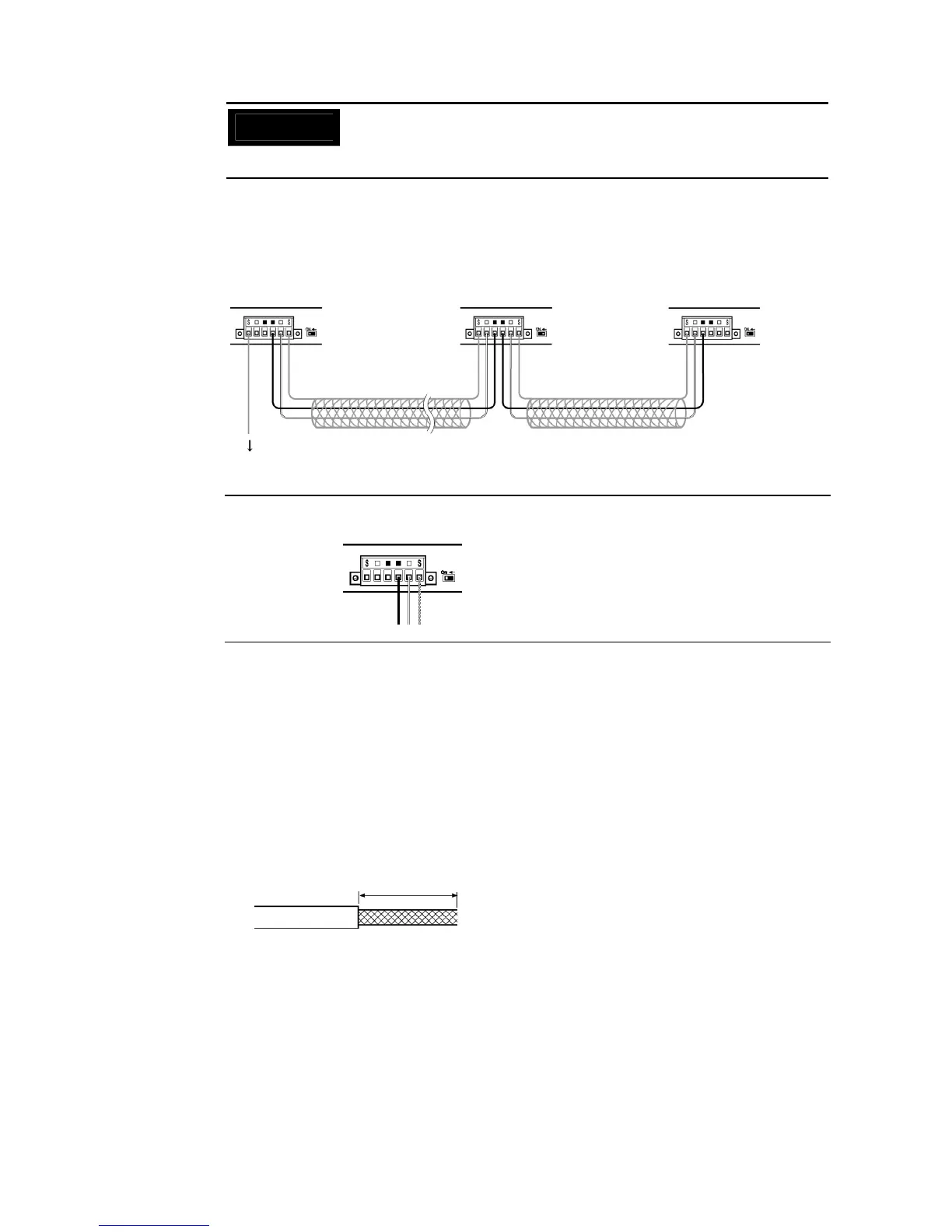
Ground all of the shield lines (including the shield line for the node at only one end of the
network) in the way shown below.
Board in the middle
of the network
Board at the end of
the network
Terminating
resistance: ON
Terminating
resistance: OFF
Terminating
resistance: ON
Board at the end of
the network
Ground
Reference
• Terminals of the same type are connected internally. They can thus be connected to
either the right or left half of the end Boards.
z Connecting Cables to Communications Connectors
When connecting a communications cable to a Controller Link Support Board, connect the
cable to the attached connector first and then attach to the connector to the Board.
Connect the communications cable to the connector using the following procedure.
1. Taking care not to damage the mesh of the shield, strip about 50 mm off the end of the
cable. Do not strip the cable too far because it may cause a short-circuit.
Approx. 50 mm
End Board