4-1 1:1 Host Connection
4-6
• Setting the Communications Board Switches (Using RS-422A)
Set the switches of the C200HX/HG/HE(-Z) Communications Board as follows:
Switch 1: 4
(Four-wire method = RS-422A)
Switch 2: ON (terminator ON = terminating resistance used)
Set the switches of the CQM1H Serial Communications Board as follows:
Two-wire/four-wire switch (WIRE): 4
(Four-wire method = RS-422A)
Terminating resistance switch (TERM): ON (terminator ON = terminating resistance used)
Serial Communications Board
(Inner Board slot 1)
Terminating resistance switch
Set to ON (right position)
Two-wire/four-wire switch
Set to 4 (right position)
• Connecting to CVM1/CV Series (-V@) PLCs (Using RS-232C/RS-422A)
PLC Setup
When using CVM1/CV-series PLCs, always set the Execute Process (Execute Control 2) in
the PLC Setup to synchronous execution.
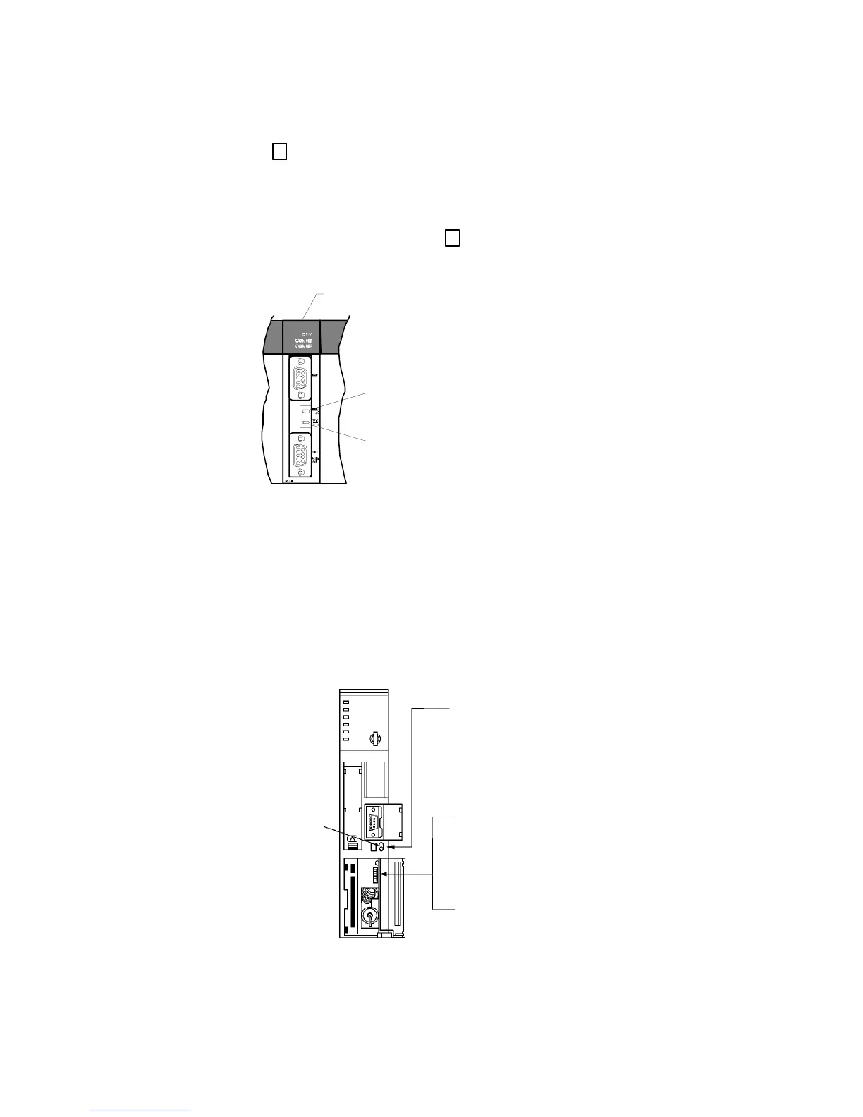
Setting the Front Panel DIP Switch
Set the DIP switch on the front panel, as shown in the following diagram.
Switch setting
Switches between RS-232C
and RS-422A
Communications setting (DIP switch pin 3)
Set pin 3 to ON (NT Link communications used).
Terminating resistance setting (DIP switch pin 6,
for RS-422A only)
Set pin 6 to ON (terminating resistance used).
Communications path
switch
(RS-232C-to-RS-422A)