4-2 1:N Host Connection
4-15
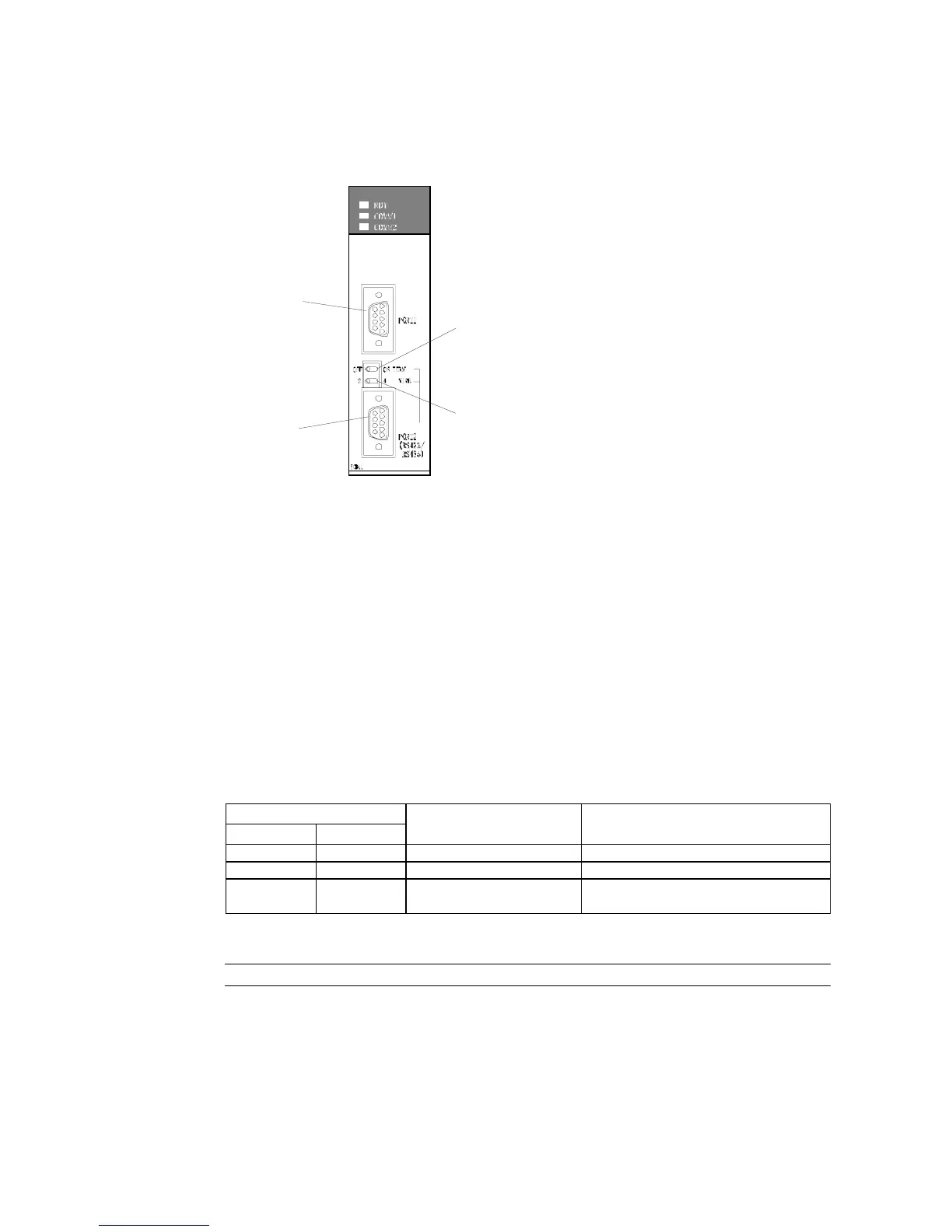
Setting the Front Panel Switches
• Using RS-422A
Port 1
RS-232C
Port 2
RS-422A
Terminating resistance switch (TERM)
Set to ON:
Terminating resistance used
(right position)
Two-wire/four-wire switch (WIRE)
For RS-422A:
Set to 4 for four-wire (right position).
Connecting to CS-series Serial Communications Units
CS-series Rack-mounted Type:
CS1W-SCU21 (Both ports 1 and 2 are RS-232C ports.)
CS1W-SCU31 (Both ports 1 and 2 are RS-422A ports.)
CPU Unit DM Area Settings
• Using RS-232C
Write the settings directly from the Programming Device or Support Software (Programming
Console or CX-Programmer) to the DM Area (Parameter Area) in the CPU Unit. After writing
the settings, enable the settings by turning ON the power again, restarting the Unit, restart-
ing the communications port, or executing the CHANGE SERIAL PORT SETUP (STUP) in-
struction.
The following table shows the allocated DM Area words and settings.
m = 30000 + 100 × unit number
Allocated DM Area words
Port 1 Port 2
Write value Settings
DM m DM m + 10 8200 1:N NT Link Mode
DM m + 1 DM m + 11 0000 to 0009 (See note 1.) Baud rate (normal)
DM m + 6 DM m + 16
000@ @: Largest unit number (1 to 7) of the
connected PTs. (See note 2.)
Note 1. Set the baud rate to a numeric value between 0000 to 0009 Hex. (The setting is the same for
any value between 0000 and 0009 Hex.)
2. When using a 1:N connection, set the value for @ to 1 or higher.
Reference When setting a 1:N NT Link in the CX-Programmer, set the baud rate to 38,400 bps.