Appendix 5 Preparing Connecting Cables
A-38
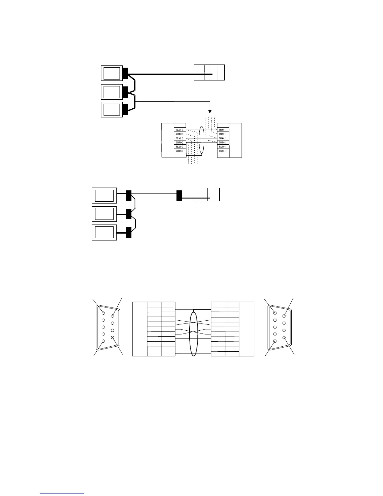
Wiring Layout between NS-AL002 and NS-AL002 (RS-422A)
Host side
NS
-
AL002
RS
-
422A
NS-AL002
NS-AL002
Shield
RS
-422A
terminal
block
RS-422A
terminal
block
Signal
Signal
FG
FG
Wiring Layout between NT-AL001 and Host (RS-422A)
NT-AL001
RS-232C
Host
NT-AL001
RS-422A
Usable Cables with Connectors
Host Link, NT Link (1:1), NT Link (N:1). +5 V provided from the PLC.
XW2Z-070T-1 (9-pin to 9-pin, 0.7 m)
XW2Z-200T-1 (9-pin to 9-pin, 2 m)
---
---
---
SD
---
---
---
Hood
1
2
3
4
5
6
7
8
9
1
2
3
4
5
6
7
8
9 SG
SG
SD
RD
RS
CS
RS
CS
RD
FG
Signal
FG
SignalPin No.
+5 V
+5 V
Pin No.
9 - pin type
Shield
9
5
6
1
PLC or PT
NT
-
AL001
5
61
9
RS-232C
CONNECTOR
9-pin type
RS-232C
CONNECTOR
When connected to a PLC with a +5-V output, an external power supply is not required
for the NT-AL001.