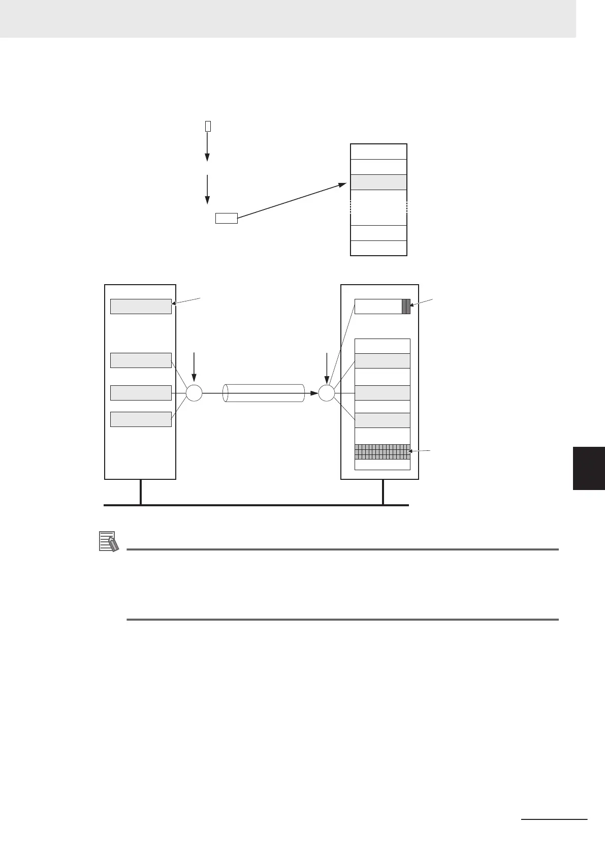
Example: Using an NJ-series CPU Unit to send the Target PLC Operating Mode of the Target Node
with an IP Address of 192.168.250.2
EtherNet/IP
NJ-series Controller
I/O memory
Controller status
CJ-series CPU Unit
Input tag set
Connection
Output tag set
Controller status (when included)
Controller status (when included)
Target data link status
Variable c
Variable b
Variable a
Controller Status
Variable h
Variable g
Variable f
_EIP_TargetPLCModeSta (Target PLC Operating Mode)
Value of last byte = 2
0
1
2
255
254
IP address = 192.168.250.2
Controller status
Target ID = #002
Additional Information
The target node ID may be duplicated depending on the IP address of the target node. In this
case, it is necessary to change the target node ID on the Network Configurator so that the
same address could not be used by more than one node.
For information on how to change the target node ID, refer to Step 4 in the procedure for Regis-
tering Devices in the Register Device List in 7-2-5 Connection Settings on page
7-36.
When you use multiple connections to communicate with one specific node, the information of the
Controller status is stored in the following variables if the Controller status is specified in the input tags
and the output tags for all the connections.
7 Tag Data Link Functions
7-11
NJ/NX-series CPU Unit Built-in EtherNet/IP Port User’s Manual (W506)
7-1 Introduction to Tag Data Links
7
7-1-6 Controller Status
 Loading...


