EasyManua.ls Logo

Omron NX102-12 Series User Manual

Omron NX102-12 Series
578 pages
To Next Page IconTo Next Page
To Previous Page IconTo Previous Page
Page #283 background imageLoading...
Page #283 background image
Var
iable D
RespSize
(Re
sponse
Data Size)
ResServiceDat
(Response Data)
Size
(Number of Elements)
ServiceDat
(Command Data)
Variable C
Variable B
Variable A
CIP communications instruction
(1)
(2)
CIPSend
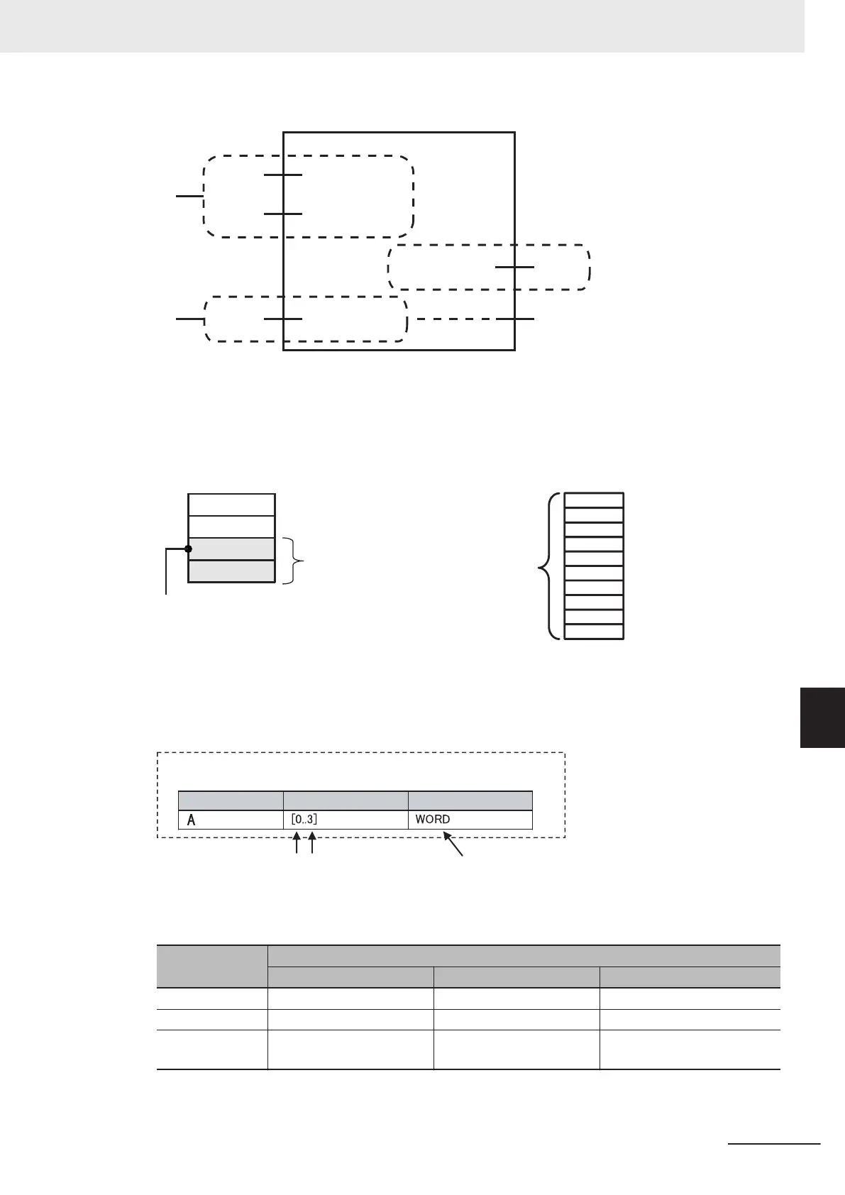
(1) Input the service data to send
The data to send is stored in array variable A.
If only certain elements are specified in array var-
iable A, specify the number of elements in varia-
ble B.
(2) Store received response data
The data that is received is stored in variable C.
The byte size of the data that was actually re-
ceived is stored in variable D.
If the service d
ata (ServiceDat) is
Array[2] and
number of elements
(Size) = 2, Array[2] and Array[3]
are sent.
Array variable: A
[0]
[1
]
[2]
[3]
Number of ele
ments: 2
[1]
[0]
[2]
[3]
[4]
[5]
[6]
[7]
[8]
[9]
Variable D
: 1
0
Array variable: C[0..9
]
Use the following procedure to create a variable in the variable table.
Specify the element first number
, the element last number, and the data type.
Example: UINT Array
Specifi
es the data type.
Specify the array element first
number and last number.
Data type
Array
Variable name
Variable table
CIP Communications Instructions That Use Array Variables
Instruction
Structure variable name
Input variable In-out variable Output variable
CIPRead --- --- DstDat (Read Data)
CIPWrite SrcDat (Write Data) --- ---
CIPSend ServiceDat (Command Da-
ta)
ResServiceDat (Response
Data)
---
8 CIP Message Communications
8-21
NJ/NX-series CPU Unit Built-in EtherNet/IP Port Users Manual (W506)
8-2 CIP Message Communications Client Function
8
8-2-6 Service Data and Response Data

Table of Contents

Question and Answer IconNeed help?

Do you have a question about the Omron NX102-12 Series and is the answer not in the manual?

Omron NX102-12 Series Specifications

General IconGeneral
ModelNX102-12 Series
Power Supply24 VDC
Built-in EtherNet/IP portYes
Built-in EtherCAT portYes
SD Memory Card SlotYes
Communication PortsUSB
Programming LanguageIEC 61131-3 (LD, FBD, ST, SFC)
Data Capacity64 KB
Memory for Variables64 KB
Operating Temperature0°C to 55°C
Storage Temperature-25°C to 75°C
Humidity10% to 90%
Vibration Resistance10 to 57 Hz, 0.075 mm amplitude, 57 to 150 Hz
TypeProgrammable Logic Controller (PLC)
Number of I/O12
I/O Points12

Summary

Terms and Conditions Agreement

Warranty, Limitations of Liability

Details Omron's warranty, limitations, and buyer remedies for products.

Safety Precautions

Precautions for Safe Use

Lists manuals to refer to for safety precautions, covering safe usage of the product.

Precautions for Correct Use

Lists manuals to refer to for correct usage, covering proper operation and performance.

Section 1 Introduction

1-3 Built-in EtherNet/IP Port

Covers specifications and part names/functions of the built-in EtherNet/IP port.

Section 2 Installing Ethernet Networks

2-1 Selecting the Network Devices

Recommends Ethernet switches and twisted-pair cables for EtherNet/IP use.

Section 3 System-defined Variables Related to the Built-in EtherNet/IP Port

3-1 System-defined Variables Related to the Built-in EtherNet/IP Port

Explains how to use system-defined variables to check the status of the built-in EtherNet/IP port.

Chapter 4 Determining IP Addresses

4-1 IP Addresses

Explains IP address configuration, allocation, subnet masks, and CIDR.

4-2 Built-in EtherNet/IP Port IP Address Settings

Details methods for setting IP addresses, including user-specified and BOOTP server options.

Chapter 5 Sysmac Studio Settings for the Built-in EtherNet/IP Port

5-1 TCP/IP Settings Display

Explains how to configure TCP/IP settings, including IP address and gateway.

Chapter 6 Testing Communications

6-1 Testing Communications

Describes how to use the PING command to test communications with the built-in EtherNet/IP port.

Chapter 7 Tag Data Link Functions

7-2 Setting Tag Data Links

Outlines the step-by-step procedure for setting tag data links, including network, tags, and connections.

Chapter 8 CIP Message Communications

Chapter 9 Socket Service

9-4 Settings Required for the Socket Services

Lists the settings required in the Unit Setup to use socket services, such as IP address and subnet mask.

Chapter 10 Modbus TCP Master Function

Chapter 11 FTP Server

11-3 Using the FTP Server Function

Outlines the procedure and required settings for using the FTP server function.

Chapter 13 Automatic Clock Adjustment

13-1 Automatic Clock Adjustment

Explains how the built-in EtherNet/IP port reads clock information from an NTP server to update the internal clock.

13-2 Procedure to Use the Automatic Clock Adjustment Function

Outlines the steps to use the automatic clock adjustment function and required settings.

Chapter 14 SNMP Agent

14-2 Procedure to Use the SNMP Agent

Outlines the steps to use the SNMP agent and the required settings in Sysmac Studio.

Chapter 15 Communications Performance and Communications Load

15-2 Adjusting the Communications Load

Explains how to adjust communications load by managing Ethernet switch functions and settings.

Chapter 16 Troubleshooting

16-1 Overview of Troubleshooting

Explains how to detect errors and find corrections for NJ/NX-series Controllers by managing errors as events.

16-2 Checking Status with the Network Configurator

Details how to check communication status and identify errors using the Network Configurator's Device Monitor function.

Appendix A Appendices

A-2 Use the Sysmac Studio to Set the Tag Data Links (EtherNet/IP Connections)

Guides users on setting up EtherNet/IP connections and tag data links using Sysmac Studio.

A-7 TCP State Transitions

A-8 Example of NX Unit Setting Using NX Configuration Object Service

Related product manuals