5-13
CHAPTER 5 Periodic Inspection
6)
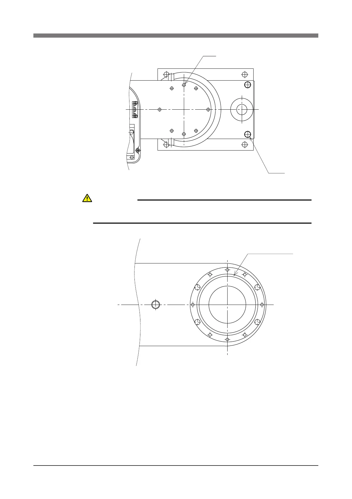
Remove the X-axis arm installation bolts (M3×40L, 8 pieces). (See Fig. 5-1.)
Fig. 5-1
O-ring
(S71 : KN3-M2159-000)
Fig. 5-2
7) Disconnect the connectors on the X-axis motor power cable XM and re-
solver cable XP.
CAUTION
AN O-RING IS FITTED TO THE X-AXIS ARM, SO BE CAREFUL NOT TO
LET IT DROP INTO THE PERIPHERAL UNIT. (SEE FIG. 5-2.)
 Loading...


