5-14
CHAPTER 5 Periodic Inspection
8) Remove the base assembly bolts (M6×14L, 6 pieces) to separate base 1 and
base 2. (See Fig. 5-1 and Fig. 5-3.)
Fig. 5-3
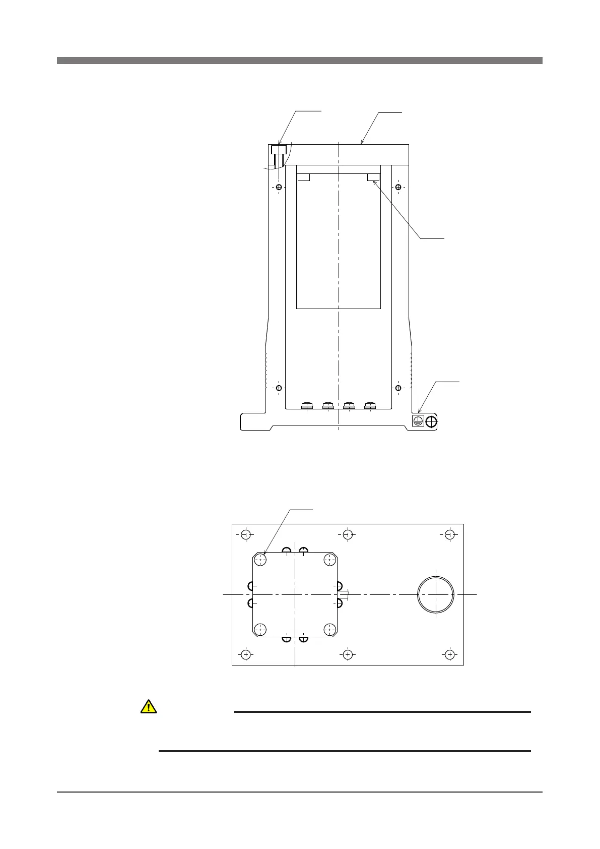
9) Remove the bolts (M5×12L, 4 pieces) securing the motor and remove the
motor from base 1. (See Fig. 5-4.)
Fig. 5-4
CAUTION
AN O-RING IS FITTED TO THE MOTOR, SO BE CAREFUL NOT TO LET IT
DROP INTO THE PERIPHERAL UNIT.
 Loading...


