5-15
CHAPTER 5 Periodic Inspection
10) Remove the wave generator from the motor shaft. The wave generator is
secured with an M3 set screw. (See Fig. 5-6.)
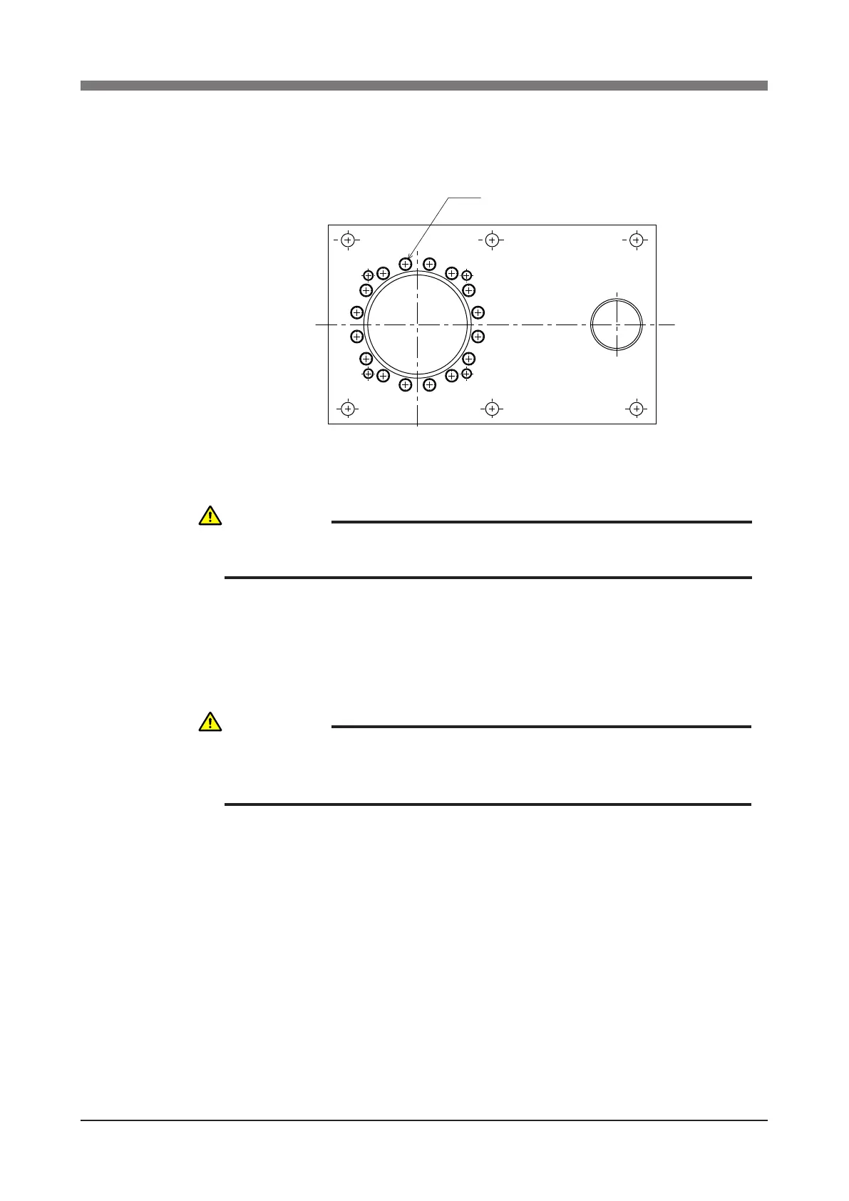
11) Remove the X-axis harmonic drive installation bolts (M3×20L, 16 pieces)
Fig. 5-5
12) Remove the X-axis harmonic drive from the top of base 1.
13) Fit an O-ring (supplied with the harmonic drive) coated with harmonic
grease into the O-ring groove on the new harmonic drive.
Apply small amounts of "Screw Lock" to the bolts (M3×20L, 16 pieces)
and tighten them to secure the harmonic drive from the backside of the
base. (See Fig. 5-5.)
CAUTION
AN O-RING IS FITTED TO THE X-AXIS HARMONIC DRIVE, SO BE
CAREFUL NOT TO LET IT DROP INTO THE PERIPHERAL UNIT.
CAUTION
DO NOT ALLOW THE O-RING TO GET CAUGHT OUT OF THE GROOVE
DURING REASSEMBLY. A PROBLEM WILL OCCUR IF THE ROBOT IS
OPERATED WITH THE O-RING LEFT CAUGHT OUT OF THE GROOVE.
 Loading...


