Fig. 5-9
11) Remove the four bolts temporarily tightened to the new harmonic drive.
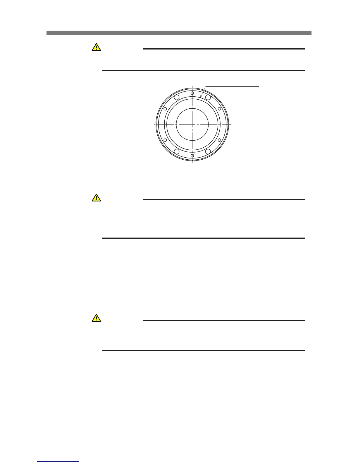
12) Fit a new O-ring coated with harmonic grease into the O-ring groove on the
Flange. (See Fig. 5-9.)
13) Place the new harmonic drive on the ange. Apply small amounts of “Screw
Lock” (thread sealer) to the bolts (M3×20, 6 pcs) and tighten them equally
from the backside of the ange to secure the harmonic drive. Next, place
the ange on the X-axis arm and tighten the bolts (M5×20) from the back-
side to secure the ange. (See Fig. 5-8.)
14) Fit an O-ring (supplied with the harmonic drive) coated with harmonic
grease into the O-ring groove on the new harmonic drive
15) Apply harmonic grease to the new wave generator and exible spline.
See Fig. 5-10 for applying grease properly.
CAUTION
AN O-RING IS FITTED TO THE FLANGE, SO BE CAREFUL NOT TO DROP
IT INTO PERIPHERAL UNITS. (SEE FIG. 5-9.)
CAUTION
REMOVE ONLY THE FOUR BOLTS SHOWN IN FIG. 5-10 AT THIS POINT.
NEVER REMOVE THE BOLTS ON THE OPPOSITE SIDE. IF THEY ARE
REMOVED, THE HARMONIC DRIVE AXIS MAY DEVIATE FROM THE
CENTER CAUSING A TROUBLE.
CAUTION
DO NOT ALLOW THE O-RING TO GET CAUGHT OUT OF THE GROOVE
DURING REASSEMBLY. A TROUBLE WILL OCCUR IF THE ROBOT IS
OPERATED WITH THE O-RING LEFT CAUGHT OUT OF THE GROOVE.
 Loading...


