5-49
CHAPTER 5 Periodic Inspection
2. Y-axis
1) Prepare the following tools and items.
• Harmonic grease 4B No.2
• Waste cloth (rag)
• Phillips-head screwdriver
• Hex wrench set
• Screw Lock (thread sealant)
• Torque-limiting wrench
• Replacement parts (See table below.)
Replacement parts
Parts name Type No .
OMRON Parts No.
Note
Harmonic drive
SHF-25-80
KN4-M2110-001
S90(JIS)
KN4-M2143-000
O-ring
Rubber wire diameter 1.78mm x Ring inner diameter 69.57mm
KN5-M2143-000
For motor
Rubber wire diameter 1.30mm x Ring inner diameter 66.50mm
KN5-M257L-000
2) Turn off the controller.
3) Place a sign indicating that the robot is being inspected, to keep others from
operating the controller switch.
4) Enter the safeguard enclosure.
5) Remove the Y-axis arm upper cover. Place the cover on the robot base
(pedestal) side with the machine harness still connected.
Refer to “7 Removing the Robot Covers” in Chapter 4 for removing the
covers.
6) Disconnect the connectors on the Y-axis motor power cable YM and
resolver cable YP.
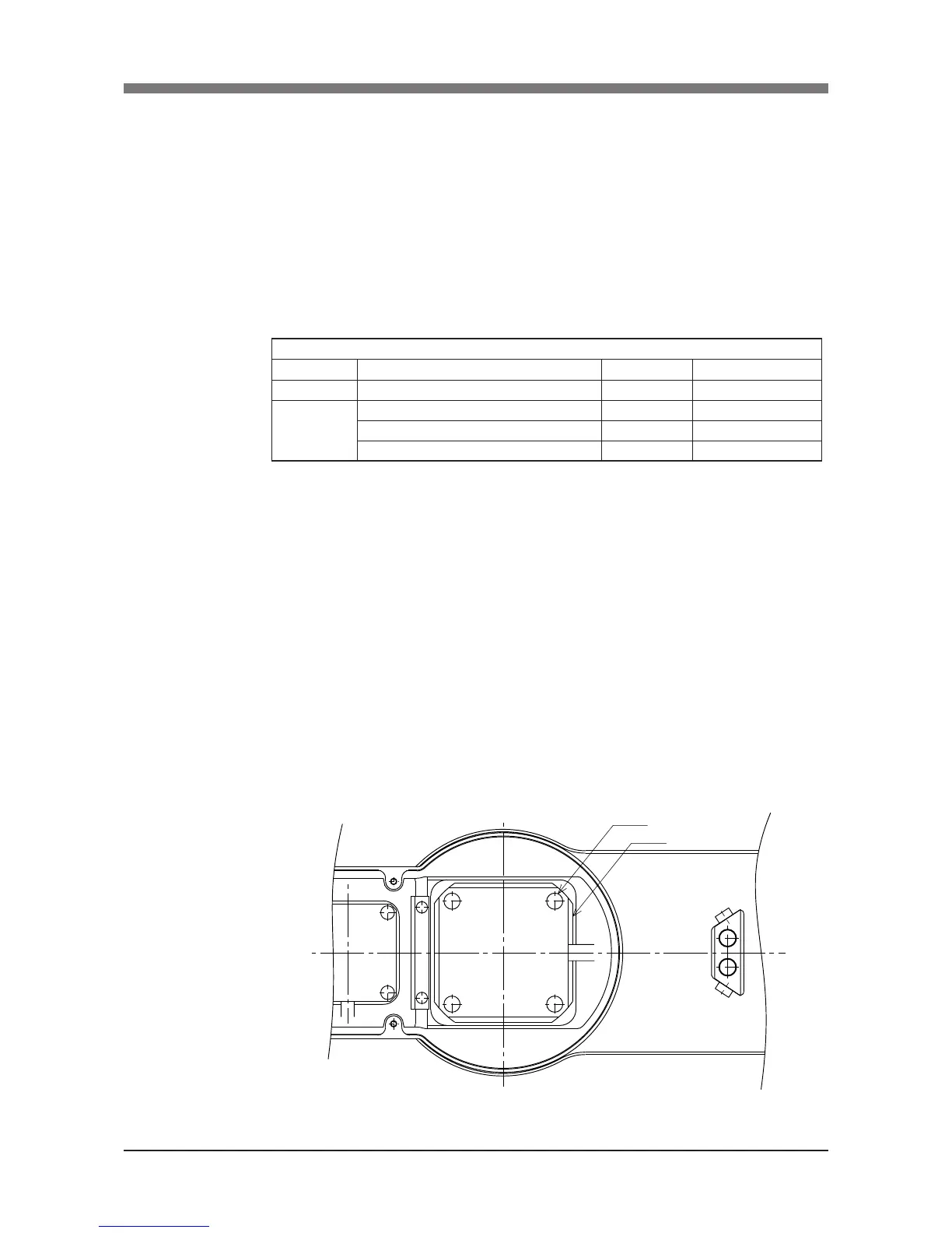
7) Remove the Y-axis motor installation bolts (M6×20L, 4 pieces) and then
remove the Y-axis motor by swaying it gently right and left.(See Fig. 5-41.)
 Loading...


